Arduino Due
Image Gallery
Overview
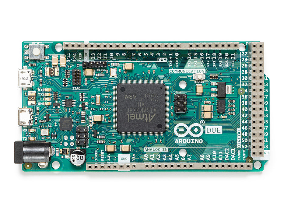
The Arduino Due was the first Arduino board based on a 32-bit ARM Cortex-M3 microcontroller, marking a significant leap in processing power and peripheral richness compared to the AVR-based boards that preceded it. At its heart is the Atmel AT91SAM3X8E running at 84 MHz, with 512 KB of flash and 96 KB of SRAM.
Released in 2012 and sharing the Mega physical form factor, the Due introduces features unavailable on 8-bit Arduino boards: two 12-bit DAC channels, a 12-bit ADC, two CAN bus controllers, and a native USB port capable of acting as a USB host or device (including HID). A second micro-USB port provides a traditional serial programming interface.
Critical notice: The Due operates at 3.3V logic. Its I/O pins are NOT 5V tolerant. Connecting 5V signals directly to any I/O pin will permanently damage the microcontroller. Most shields designed for the Uno or Mega (which use 5V logic) are not directly compatible without level shifting.
Quick Overview
| Property | Value |
|---|---|
| Microcontroller | AT91SAM3X8E (32-bit ARM Cortex-M3) |
| Clock Speed | 84 MHz |
| Operating Voltage | 3.3V (NOT 5V tolerant on I/O) |
| Input Voltage (recommended) | 7–12V |
| Digital I/O Pins | 54 (12 with PWM) |
| Analog Input Pins | 12 (12-bit ADC) |
| Analog Output (DAC) | 2 × 12-bit (DAC0, DAC1) |
| Flash Memory | 512 KB |
| SRAM | 96 KB (64 KB + 32 KB dual banks) |
| Hardware UARTs | 4 (Serial, Serial1, Serial2, Serial3) |
| CAN Controllers | 2 (CAN0, CAN1) |
| USB Ports | 2 × micro-USB (Programming + Native USB) |
| Dimensions | 101.6 × 53.4 mm |
Key Features
- 32-bit ARM Cortex-M3 at 84 MHz — dramatically more processing power than AVR-based Arduino boards
- 512 KB flash and 96 KB SRAM for large sketches and data buffers
- Two 12-bit DAC channels providing true analog voltage output (not PWM)
- 12-bit ADC on all 12 analog inputs for high-resolution sensor readings
- Two CAN 2.0A/B controllers for automotive and industrial communication
- Native USB port with HID support — act as USB keyboard, mouse, or MIDI device
- Programming USB port provides a traditional serial upload path without interfering with the native USB application
- Four hardware UART ports for multi-device serial communication
- Two I2C buses and two SPI buses for versatile peripheral connectivity
- Same physical form factor as the Arduino Mega 2560
Technical Specifications
| Specification | Value |
|---|---|
| Microcontroller | Atmel AT91SAM3X8E |
| Architecture | 32-bit ARM Cortex-M3 |
| Clock Speed | 84 MHz |
| Operating Voltage | 3.3V |
| Recommended Input Voltage | 7–12V |
| Digital I/O Pins | 54 |
| PWM Pins | 12 |
| Analog Input Pins | 12 (12-bit ADC) |
| Analog Output (DAC) | 2 × 12-bit (DAC0 on A0, DAC1 on A1) |
| DC Current per I/O Pin | 130 mA (total), 3 mA per pin recommended |
| Flash Memory | 512 KB |
| SRAM | 96 KB (64 KB + 32 KB) |
| Hardware UARTs | 4 (Serial, Serial1, Serial2, Serial3) |
| I2C | 2 |
| SPI | 1 (ICSP header) + 1 (SPI header, pins 10–13) |
| CAN Controllers | 2 (CAN0, CAN1 — CAN 2.0A/B) |
| USB | 2 × micro-USB (Programming port + Native USB port) |
| Dimensions | 101.6 × 53.4 mm |
Pinout
Digital I/O Pins
| Pin Range | Function |
|---|---|
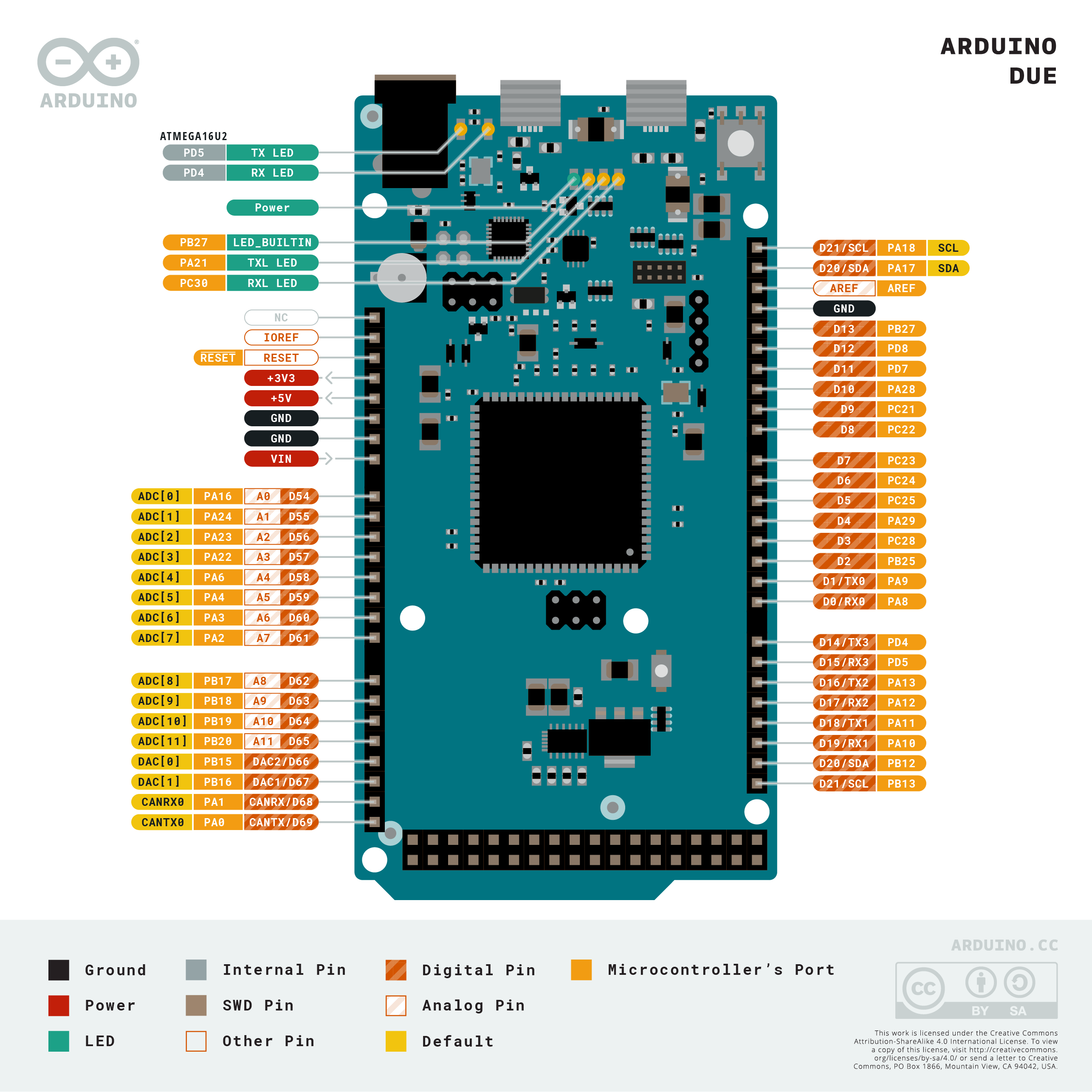
| D0 (RX0) / D1 (TX0) | Hardware Serial (Programming port) |
| D2–D13 | General digital I/O; D3, D5, D6, D9, D10, D11, D13 PWM |
| D14 (TX3) / D15 (RX3) | Hardware Serial3 |
| D16 (TX2) / D17 (RX2) | Hardware Serial2 |
| D18 (TX1) / D19 (RX1) | Hardware Serial1 |
| D20 (SDA) / D21 (SCL) | I2C bus 1 |
| D70 (SDA1) / D71 (SCL1) | I2C bus 2 |
| D50 (MISO) / D51 (MOSI) / D52 (SCK) / D53 (SS) | SPI bus |
Analog Pins
| Pin | Function |
|---|---|
| A0 | Analog input + DAC0 output |
| A1 | Analog input + DAC1 output |
| A2–A11 | Analog input (12-bit ADC) |
Power Pins
| Pin | Description |
|---|---|
| VIN | 7–12V input (same as barrel jack) |
| 5V | 5V output (from regulator) — for powering peripherals only, NOT for I/O logic |
| 3.3V | 3.3V regulated output |
| GND | Ground |
| RESET | Pull LOW to reset |
| IOREF | 3.3V reference for shields |
Power
The Arduino Due can be powered via:
- Programming micro-USB: 5V from host, sufficient for development use.
- Native micro-USB: 5V from host if the native port is connected.
- DC Barrel Jack: 7–12V DC (center positive). On-board regulator provides 3.3V.
- VIN Pin: Same range as the barrel jack.
The 5V pin on the Due outputs 5V but this voltage is only used for powering compatible peripherals — the MCU itself runs at 3.3V, and the I/O pins operate at 3.3V exclusively.
Microcontroller
The AT91SAM3X8E is a Cortex-M3 processor from Atmel (now Microchip). Key architectural details:
- 32-bit RISC architecture with Thumb-2 instruction set
- 84 MHz maximum clock with hardware multiply and divide
- Two independent SRAM banks (64 KB + 32 KB) allowing simultaneous access from DMA and CPU
- DMA controller (PDC/DMA) for zero-CPU-overhead peripheral transfers
- Hardware floating-point is NOT present in Cortex-M3 (present in M4/M7); software FPU is used
Digital-to-Analog Converter
The Due includes two independent 12-bit DAC channels, which are a notable advantage over most Arduino boards that rely on PWM for analog-like output.
| Channel | Pin | Resolution | Notes |
|---|---|---|---|
| DAC0 | A0 | 12-bit | True analog voltage output, 0–3.3V range |
| DAC1 | A1 | 12-bit | True analog voltage output, 0–3.3V range |
The DACs are ideal for audio signal generation, waveform synthesis, and precision analog control. The analogWrite() function on DAC pins outputs a true DC voltage, not a PWM signal.
HID Support
The Native USB port on the Due (connected directly to the AT91SAM3X8E) supports USB HID without any bridge chip. This means the Due can emulate USB keyboards, mice, and other HID devices.
The Keyboard and Mouse libraries work on the Due via the native USB port. Upload via the Programming port when using HID sketches, to avoid losing the upload connection.
Getting Started
What You Need
- Arduino Due
- Two micro-USB cables (one for Programming port, one optional for Native port)
- Computer with Arduino IDE installed
Steps
- Connect the Programming port (the micro-USB closest to the power barrel jack) to your computer.
- Open the Arduino IDE.
- Install the SAM board package: Tools > Board > Boards Manager, search for "Arduino SAM Boards" and install.
- Select Tools > Board > Arduino SAM Boards > Arduino Due (Programming Port).
- Select the correct COM port under Tools > Port.
- Upload the Blink example.
Blink Example
Programming
The Due has two upload paths:
| Port | Use Case |
|---|---|
| Programming Port (micro-USB) | Standard sketch upload; uses ATmega16U2-style reset; always available |
| Native USB Port (micro-USB) | HID / USB device sketches; direct ARM USB; may disconnect during upload |
- Board package: Arduino SAM Boards (installed via Boards Manager)
- Programmer: No external programmer needed for normal use; JTAG available for advanced debugging
- Upload protocol: bossac (SAM-BA bootloader)
- Auto-reset: Supported on the Programming port via 1200-baud touch
Shield Compatibility
WARNING: The Due operates at 3.3V logic. I/O pins are NOT 5V tolerant. Connecting 5V signals to the Due's I/O pins will permanently damage the microcontroller.
| Shield Type | Compatibility |
|---|---|
| 5V Arduino Uno / Mega shields | NOT compatible without level shifting — risk of permanent damage |
| 3.3V shields | Compatible |
| Shields using only I2C/SPI with 3.3V logic | May work; verify signal levels first |
| Mega form factor shields (physical fit) | Physically fit, but verify voltage levels |
Before connecting any existing shield to the Due, verify that all signal lines operate at 3.3V. Level-shifting modules (e.g., TXB0108, 4-channel bidirectional level shifters) are required for mixing 5V and 3.3V devices.
CAN Bus
The Due includes two CAN 2.0A/B controllers (CAN0 and CAN1), making it suitable for automotive and industrial applications.
| Controller | Pins | Standard |
|---|---|---|
| CAN0 | CANRX0 (pin 69), CANTX0 (pin 68) | CAN 2.0A/B |
| CAN1 | CANRX1 (pin 67), CANTX1 (pin 66) | CAN 2.0A/B |
An external CAN transceiver (such as MCP2551) is required to connect the CAN controllers to a physical CAN bus. The due_can library and similar third-party libraries provide CAN communication support.
Package Contents
| Item | Quantity |
|---|---|
| Arduino Due board | 1 |
Micro-USB cables are not included. Two are useful — one for the Programming port and one for the Native USB port.
Applications
- High-speed signal processing requiring 32-bit arithmetic
- Audio synthesis and playback using the dual 12-bit DAC
- Automotive prototyping using the dual CAN bus controllers
- USB HID device emulation (keyboard, mouse, MIDI)
- Precision analog output applications (waveform generators, DAC-driven control systems)
- Projects requiring large RAM buffers (image processing, communication stacks)
- Industrial control systems requiring multiple serial buses
Where to Buy
Equivalent Boards
| Board | Key Difference |
|---|---|
| Arduino GIGA R1 WiFi | Newer dual-core 32-bit ARM (M7+M4), built-in Wi-Fi/BT, Mega form factor |
| Arduino Mega 2560 | 8-bit AVR at 16 MHz, 5V logic, highly shield-compatible, no DAC or CAN |
| Arduino Zero | Cortex-M0+ at 48 MHz, Uno form factor, 3.3V, single DAC, on-board debugger |
Documentation
Notes
- 3.3V I/O is the single most important fact about the Due. Every shield, sensor, and module connected to the I/O pins must be verified to operate at 3.3V. There is no internal protection against 5V signals.
- The 5V pin on the headers outputs 5V (sourced from the USB or regulator) and can be used to power 5V peripherals, but must never be connected back to an I/O pin.
- When using the Native USB port for HID sketches, always upload via the Programming port. Switching to native USB on the upload target will cause the IDE to lose connection.
- The Due's SAM-BA bootloader can be triggered by double-pressing the ERASE button followed by the RESET button, which fully erases the flash — useful for recovery.
Community
- Arduino Forum — official community for questions and projects
- Arduino Discord — real-time chat with the Arduino community
- r/arduino (Reddit) — share projects and ask questions
- Arduino Project Hub — browse community-submitted projects
Revision History
| Version | Date | Notes |
|---|---|---|
| v1.0 | 2026-06 | Initial entry |