Arduino GIGA R1 WiFi
Image Gallery
Overview
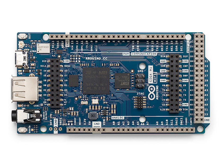
The Arduino GIGA R1 WiFi is the most capable board in the Arduino Mega form factor family. Released in 2022, it is built around the STM32H747XI — a dual-core processor combining an ARM Cortex-M7 running at 480 MHz and an ARM Cortex-M4 running at 240 MHz. Both cores can be programmed simultaneously using the Arduino IDE, with the M7 handling the primary application and the M4 available via remote procedure calls (RPC).
Beyond raw processing power, the GIGA R1 WiFi adds connectivity and multimedia capabilities absent from previous Mega-class boards: integrated Wi-Fi 802.11 b/g/n, Bluetooth 5.0, a 3.5 mm audio jack for I2S audio input/output, a 22-pin MIPI camera connector, and a 22-pin MIPI display connector. USB-C replaces the older USB-B and micro-USB connectors found on prior boards.
The board also includes 8 MB external SDRAM and 16 MB external QSPI flash in addition to the 1 MB internal SRAM and 2 MB internal flash of the STM32H747XI, making it suitable for memory-intensive applications including machine learning inference, audio processing, and graphical user interfaces.
Quick Overview
| Property | Value |
|---|---|
| Microcontroller | STM32H747XI (dual-core ARM) |
| Primary Core | Cortex-M7 at 480 MHz |
| Secondary Core | Cortex-M4 at 240 MHz |
| Operating Voltage | 3.3V I/O |
| Input Voltage | 6–24V |
| Internal SRAM | 1 MB |
| External SDRAM | 8 MB |
| Internal Flash | 2 MB |
| External QSPI Flash | 16 MB |
| Wireless | Wi-Fi 802.11 b/g/n + Bluetooth 5.0 |
| Digital I/O Pins | 76 |
| Analog Input Pins | 12 (16-bit ADC) |
| DAC | 2 × 12-bit |
| USB | USB-C (native OTG + programming) |
| Audio | 3.5 mm stereo jack (I2S) |
| Camera Connector | 22-pin MIPI CSI |
| Display Connector | 22-pin MIPI DSI |
| Dimensions | 101.6 × 53.4 mm |
Key Features
- Dual-core STM32H747XI: Cortex-M7 at 480 MHz for main application, Cortex-M4 at 240 MHz for parallel tasks
- Integrated Wi-Fi 802.11 b/g/n and Bluetooth 5.0 via Murata LBAD0ZZ1WA module (u-blox chipset)
- 8 MB external SDRAM and 16 MB external QSPI flash for large data and asset storage
- 3.5 mm audio jack with I2S support for audio input and output
- 22-pin MIPI CSI camera connector for compatible camera modules
- 22-pin MIPI DSI display connector for compatible display modules
- USB-C port with native USB OTG support (host or device)
- 76 digital I/O pins in the Mega form factor — compatible with many Mega shields (verify 3.3V levels)
- Two 12-bit DAC channels for true analog voltage output
- 12 analog inputs with 16-bit ADC resolution
- Full HID support via native USB
Technical Specifications
| Specification | Value |
|---|---|
| Microcontroller | STM32H747XI |
| Primary Core | ARM Cortex-M7 at 480 MHz |
| Secondary Core | ARM Cortex-M4 at 240 MHz |
| Operating Voltage | 3.3V |
| Input Voltage | 6–24V |
| Internal SRAM | 1 MB |
| External SDRAM | 8 MB (32-bit bus) |
| Internal Flash | 2 MB |
| External QSPI Flash | 16 MB |
| Digital I/O Pins | 76 |
| PWM Pins | Available on multiple pins (see pinout) |
| Analog Input Pins | 12 (16-bit ADC) |
| DAC | 2 × 12-bit |
| Hardware UARTs | 4 |
| I2C | 2 |
| SPI | 2 |
| USB | USB-C (native USB OTG) |
| Wireless Module | Murata LBAD0ZZ1WA |
| Wi-Fi | 802.11 b/g/n (2.4 GHz) |
| Bluetooth | 5.0 (BLE and classic) |
| Audio | 3.5 mm jack (I2S in/out) |
| Camera Connector | 22-pin MIPI CSI |
| Display Connector | 22-pin MIPI DSI |
| Dimensions | 101.6 × 53.4 mm |
Pinout
Digital I/O
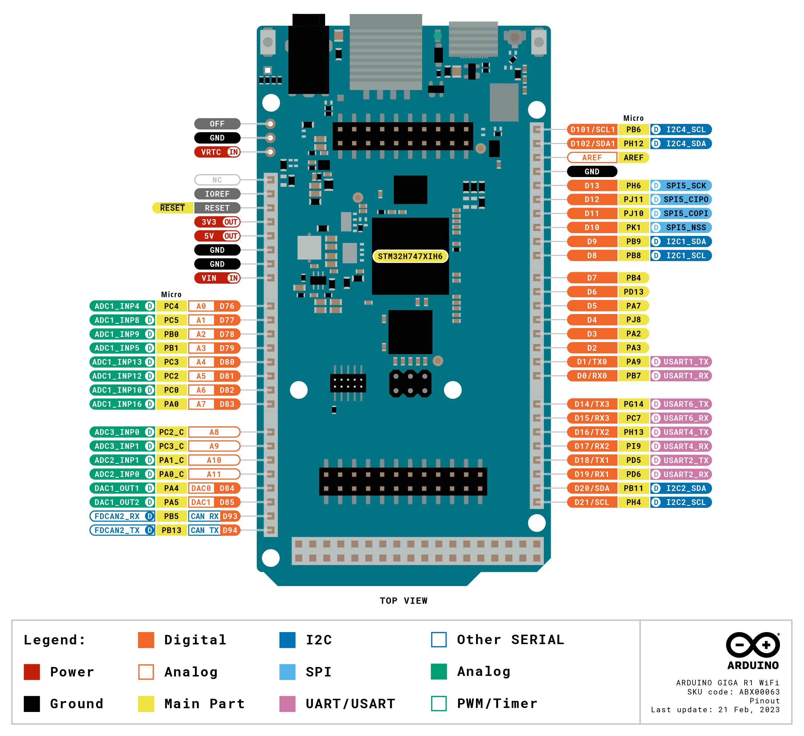
The GIGA R1 WiFi provides 76 digital I/O pins across the extended Mega-compatible headers. Many pins support PWM, with specific capabilities depending on the STM32H7 timer assignments.
| Pin Group | Function |
|---|---|
| D0 / D1 | Hardware Serial RX/TX (Serial1) |
| D2–D13 | General digital I/O, PWM-capable on several pins |
| D14–D21 | General digital I/O; D20 SDA / D21 SCL (I2C1) |
| D50–D53 | SPI bus (MISO/MOSI/SCK/SS) |
| D54–D76 | Extended I/O (Mega extra rows) |
Analog Pins
| Pin | Notes |
|---|---|
| A0–A11 | 12-channel 16-bit ADC |
| A0 | Also DAC0 output (12-bit) |
| A1 | Also DAC1 output (12-bit) |
Power Pins
| Pin | Description |
|---|---|
| VIN | 6–24V input |
| 5V | 5V regulated output (for peripherals) |
| 3.3V | 3.3V regulated output |
| GND | Ground |
| IOREF | 3.3V reference |
Power
The GIGA R1 WiFi can be powered by:
- USB-C: 5V from host computer — sufficient for development and moderate peripheral loads.
- DC Barrel Jack: 6–24V DC. The wider voltage range compared to older Arduino boards allows use with 12V and 24V power supplies common in industrial and automotive settings.
- VIN Pin: Same range as the barrel jack.
The board's on-board regulators supply 3.3V for the MCU and 5V for compatible peripherals. Due to the high-performance processor and wireless module, power consumption is higher than classic AVR-based boards — account for this when designing battery-powered applications.
Microcontroller
The STM32H747XI from STMicroelectronics is the most powerful MCU ever used in an Arduino board at the time of the GIGA R1 WiFi's release.
| Attribute | M7 Core | M4 Core |
|---|---|---|
| Architecture | ARM Cortex-M7 | ARM Cortex-M4 |
| Clock Speed | 480 MHz | 240 MHz |
| FPU | Double-precision | Single-precision |
| Primary Use | Main application | Parallel/real-time tasks |
Both cores share access to the same peripherals and memory, with hardware semaphores used for synchronization. The Arduino framework runs the M7 as the primary core. The M4 is programmed separately (as a second sketch) and communicates with the M7 via shared memory and the RPC library.
Wireless Connectivity
The GIGA R1 WiFi uses the Murata LBAD0ZZ1WA module (powered by u-blox chipset) to provide dual wireless connectivity.
| Technology | Standard | Notes |
|---|---|---|
| Wi-Fi | 802.11 b/g/n (2.4 GHz) | Station and Access Point modes supported |
| Bluetooth | 5.0 (BLE + Classic) | BLE for low-energy applications |
Wi-Fi Example
Digital-to-Analog Converter
The GIGA R1 WiFi includes two 12-bit DAC channels providing true analog voltage output on A0 and A1.
| Channel | Pin | Resolution | Output Range |
|---|---|---|---|
| DAC0 | A0 | 12-bit | 0–3.3V |
| DAC1 | A1 | 12-bit | 0–3.3V |
The analogWriteResolution(12) function enables full 12-bit DAC output. DAC output is ideal for audio waveform generation, smooth analog control signals, and test signal generation.
HID Support
The GIGA R1 WiFi supports USB HID via its native USB-C port. The board can emulate USB keyboards, mice, MIDI devices, and other HID peripherals.
Getting Started
What You Need
- Arduino GIGA R1 WiFi
- USB-C cable
- Computer with Arduino IDE 2.x installed
Steps
- Connect the GIGA R1 WiFi to your computer via USB-C.
- Open the Arduino IDE.
- Install the board package: Tools > Board > Boards Manager, search for "Arduino Mbed OS GIGA Boards" and install.
- Select Tools > Board > Arduino Mbed OS GIGA Boards > Arduino GIGA R1 WiFi.
- Select the correct COM port under Tools > Port.
- Upload the Blink sketch to verify the setup.
Blink Example
Programming
The GIGA R1 WiFi uses the Arduino Mbed OS GIGA Boards package. Key details:
- Board package: Arduino Mbed OS GIGA Boards (Boards Manager)
- Upload protocol: DFU (Device Firmware Update) over USB-C
- Auto-reset: Double-press the RESET button to enter bootloader mode if needed
- M4 core programming: A separate sketch compiled for the M4 is flashed alongside the M7 sketch via the RPC framework
- Over-the-Air (OTA) updates: Supported via the ArduinoOTA library over Wi-Fi
Shield Compatibility
The GIGA R1 WiFi uses the Mega physical form factor and is partially compatible with Mega shields. However, the board operates at 3.3V I/O logic.
| Shield Type | Compatibility |
|---|---|
| Arduino Mega 5V shields | NOT directly compatible — I/O is 3.3V; verify 5V tolerance before connecting |
| 3.3V Mega shields | Compatible |
| GIGA-specific shields/accessories | Fully compatible |
| Shields using only I2C/SPI | May work if levels are compatible; check datasheet |
Some GIGA R1 WiFi I/O pins are marked as 5V tolerant in the STM32H747 datasheet — consult the official pinout documentation to identify which pins accept 5V input before connecting 5V signals.
Package Contents
| Item | Quantity |
|---|---|
| Arduino GIGA R1 WiFi board | 1 |
A USB-C cable is not included. Any USB-C cable supporting data transfer is compatible.
Applications
- Dual-core parallel processing projects
- Machine learning inference at the edge (TensorFlow Lite Micro)
- Wi-Fi and Bluetooth IoT applications
- Audio processing and synthesis using the I2S audio jack
- Camera-based vision projects with compatible MIPI CSI modules
- Display-connected user interface applications
- USB HID device prototyping
- Industrial control with multiple communication buses
- Advanced robotics requiring real-time processing on the M4 and high-level logic on the M7
Where to Buy
Equivalent Boards
| Board | Key Difference |
|---|---|
| Arduino Due | Older single-core Cortex-M3 at 84 MHz, no wireless, same Mega form factor |
| Arduino Mega 2560 | 8-bit AVR at 16 MHz, 5V logic, far fewer features, very shield-compatible |
| Arduino Portenta H7 | Same STM32H747 MCU, smaller industrial form factor, more I/O options via carrier boards |
Documentation
Notes
- The GIGA R1 WiFi requires the Arduino Mbed OS GIGA Boards package — it is not available under the classic AVR or SAM board packages.
- When using HID features via the native USB-C port, upload sketches while the board is in DFU mode (double-press RESET) to avoid connection interruption.
- The M4 core sketch must be compiled and uploaded separately from the M7 core sketch. The Arduino IDE handles this through the "Arduino GIGA R1 WiFi (M4)" board target.
- Some I/O pins on the STM32H747 are 5V tolerant as inputs — consult the official pinout reference to identify these pins before mixing logic levels.
- The Murata wireless module requires the "WiFi" library bundled with the Mbed OS GIGA Boards package; ensure the package is up to date for the latest connectivity fixes.
Community
- Arduino Forum — official community for questions and projects
- Arduino Discord — real-time chat with the Arduino community
- r/arduino (Reddit) — share projects and ask questions
- Arduino Project Hub — browse community-submitted projects
Revision History
| Version | Date | Notes |
|---|---|---|
| v1.0 | 2026-06 | Initial entry |