
Arduino Leonardo
Image Gallery
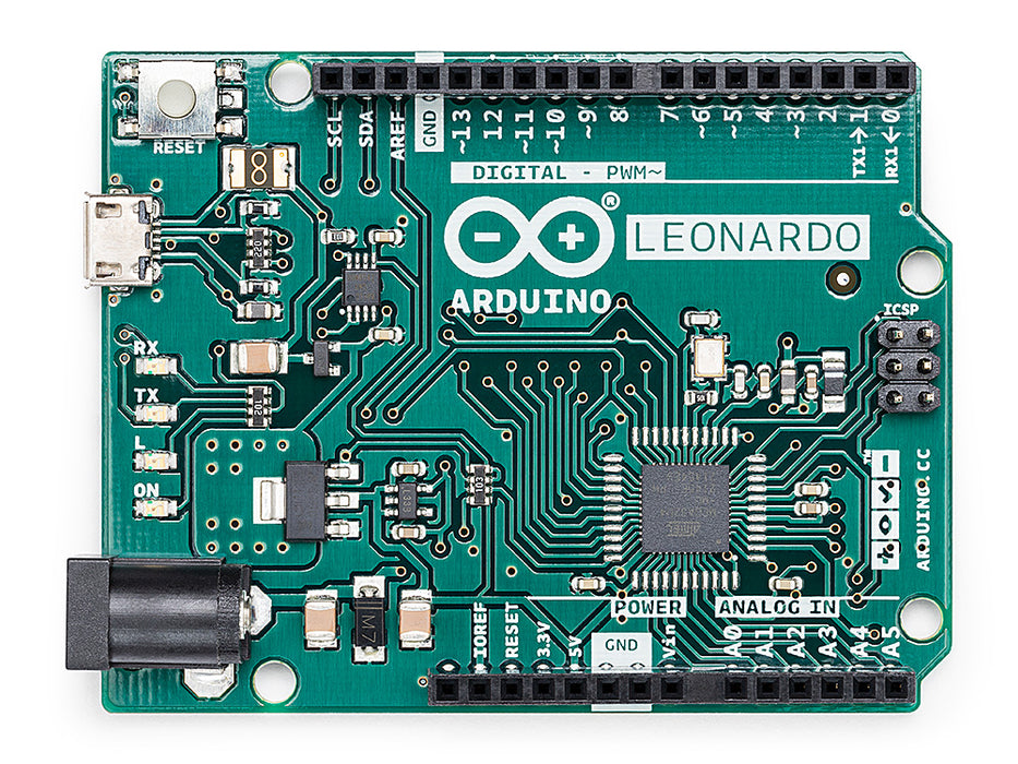
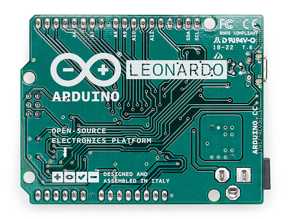
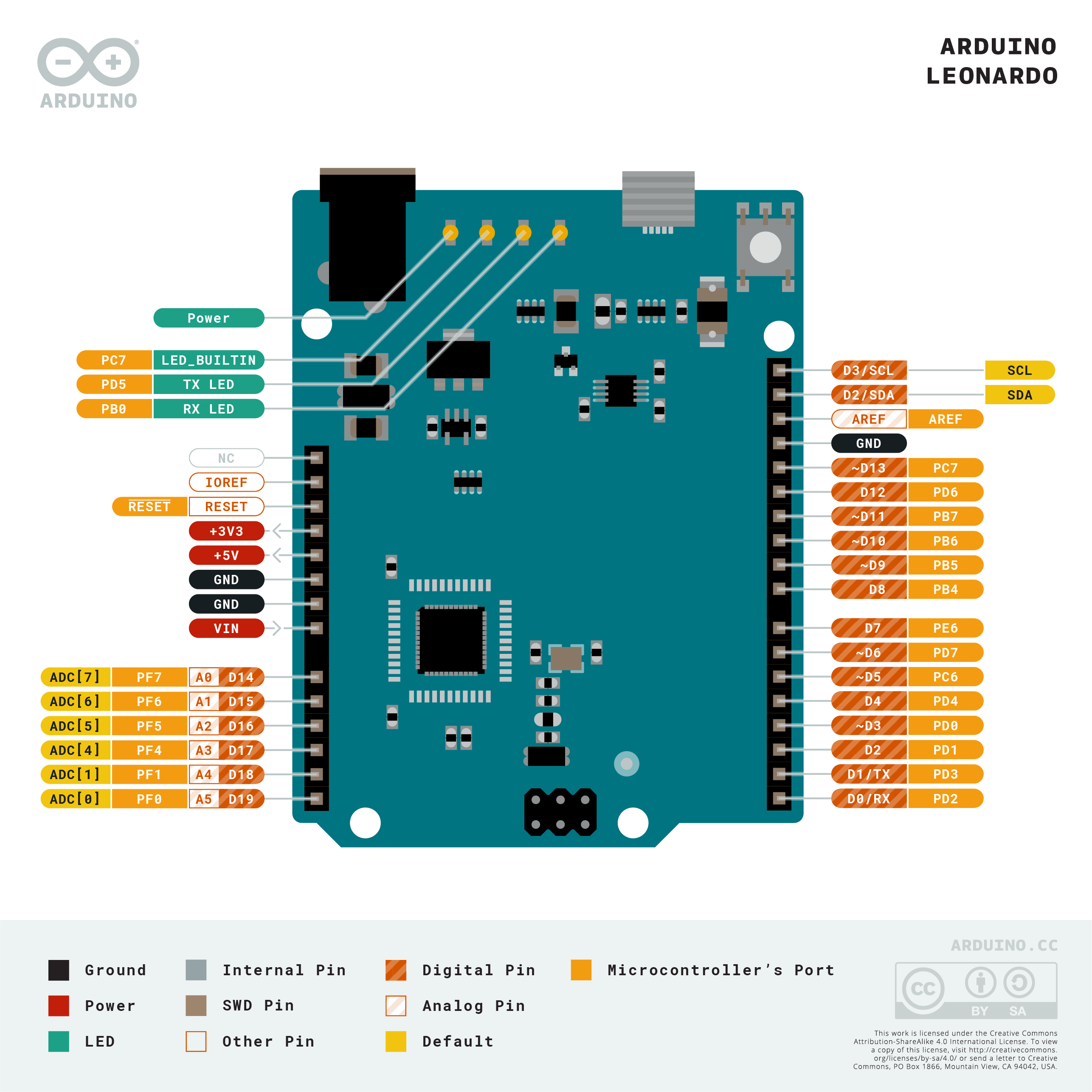
Overview
The Arduino Leonardo is an 8-bit AVR board built around the ATmega32U4 microcontroller — the key distinction being that the ATmega32U4 includes a built-in USB controller. Unlike the Arduino Uno, which uses a separate ATmega16U2 chip to bridge USB-to-serial, the Leonardo's MCU handles USB communication directly. This native USB capability enables the board to appear to a host computer as a USB keyboard, mouse, joystick, MIDI device, or any other USB HID class device — entirely in software, without additional hardware.
Released in 2012, the Leonardo shares the same physical form factor as the Arduino Uno and is compatible with most Uno shields. It features 20 digital I/O pins (with 7 PWM-capable), 12 analog inputs, and one hardware UART (Serial1). The USB virtual serial port (Serial) is independent from the hardware UART, meaning both can be used simultaneously.
The native USB design also introduces one notable behavioral difference from the Uno: there is no separate serial chip to maintain the USB connection during reset, so a brief disconnect occurs when the board resets during upload.
Quick Overview
| Property | Value |
|---|---|
| Microcontroller | ATmega32U4 (8-bit AVR) |
| Clock Speed | 16 MHz |
| Operating Voltage | 5V |
| Input Voltage (recommended) | 7–12V |
| Digital I/O Pins | 20 (7 with PWM) |
| Analog Input Pins | 12 (A0–A11) |
| Flash Memory | 32 KB (4 KB used by bootloader) |
| SRAM | 2.5 KB |
| EEPROM | 1 KB |
| Hardware UART | 1 (Serial1 on D0/D1) |
| USB | micro-USB (native HID — ATmega32U4 is the USB controller) |
| I2C | 1 (D2 SDA, D3 SCL) |
| SPI | 1 (ICSP header) |
| Dimensions | 68.6 × 53.4 mm |
Key Features
- Native USB HID via the ATmega32U4's built-in USB controller — no separate bridge chip
- Emulate USB keyboard, mouse, joystick, or MIDI device with standard Arduino libraries
- 20 digital I/O pins with 7 PWM outputs
- 12 analog input channels (A0–A5 on dedicated pins; A6–A11 shared with digital pins D4, D6, D8, D9, D10, D12)
- Simultaneous USB serial (CDC) and hardware UART (Serial1) — useful for debugging HID sketches
- Compatible with many Arduino Uno shields (same 5V logic and header layout)
- Single hardware UART (Serial1) on D0/D1 for communication with external serial devices
- On-board ICSP header for SPI peripherals and bootloader programming
Technical Specifications
| Specification | Value | |
|---|---|---|
| Microcontroller | ATmega32U4 | |
| Architecture | 8-bit AVR | |
| Clock Speed | 16 MHz | |
| Operating Voltage | 5V | |
| Recommended Input Voltage | 7–12V | |
| Maximum Input Voltage | 20V | |
| Digital I/O Pins | 20 | |
| PWM Pins | 7 (D3, D5, D6, D9, D10, D11, D13) | |
| Analog Input Pins | 12 (A0–A5 dedicated; A6–A11 on digital pins) | |
| DC Current per I/O Pin | 40 mA | |
| DC Current for 3.3V Pin | 50 mA | |
| Flash Memory | 32 KB (4 KB bootloader) | |
| SRAM | 2.5 KB | |
| EEPROM | 1 KB | |
| Hardware UART | 1 (Serial1, D0=RX1, D1=TX1) | |
| USB Serial (CDC) | Serial (via USB — separate from Serial1) | |
| I2C | 1 (D2 SDA, D3 SCL) | |
| SPI | 1 (ICSP header | MISO, MOSI, SCK, SS) |
| USB | micro-USB (native, ATmega32U4 integrated controller) | |
| On-Board LED | Pin 13 | |
| Dimensions | 68.6 × 53.4 mm |
Pinout
Digital I/O Pins
| Pin | Function | Notes |
|---|---|---|
| D0 (RX1) | Hardware Serial1 RX | Also general digital I/O |
| D1 (TX1) | Hardware Serial1 TX | Also general digital I/O |
| D2 | Digital I/O / SDA | I2C data line |
| D3 | Digital I/O / SCL / PWM | I2C clock line, PWM output |
| D4 | Digital I/O / A6 | Dual-function analog input |
| D5 | Digital I/O / PWM | PWM output |
| D6 | Digital I/O / A7 / PWM | Dual-function analog, PWM |
| D7 | Digital I/O | |
| D8 | Digital I/O / A8 | Dual-function analog input |
| D9 | Digital I/O / A9 / PWM | Dual-function analog, PWM |
| D10 | Digital I/O / A10 / PWM | Dual-function analog, PWM |
| D11 | Digital I/O / PWM | PWM output |
| D12 | Digital I/O / A11 | Dual-function analog input |
| D13 | Digital I/O / PWM / LED | Built-in LED, PWM output |
Analog Pins
| Pin | Notes |
|---|---|
| A0–A5 | Dedicated analog input pins (also usable as digital I/O) |
| A6–A11 | Shared with D4, D6, D8, D9, D10, D12 — analog input only on those physical pins |
Power Pins
| Pin | Description |
|---|---|
| VIN | 7–12V input (barrel jack equivalent) |
| 5V | Regulated 5V output |
| 3.3V | 3.3V output (50 mA max) |
| GND | Ground |
| RESET | Pull LOW to reset |
| IOREF | 5V reference for shields |
| AREF | Analog reference for ADC |
Power
The Arduino Leonardo can be powered from:
- micro-USB: 5V from the connected host computer.
- DC Barrel Jack: 7–12V DC, regulated on-board to 5V.
- VIN Pin: 7–12V from an external supply on the headers.
Each I/O pin can source or sink up to 40 mA. The 3.3V pin supplies up to 50 mA. Total I/O current draw should be managed to avoid overloading the on-board regulator.
HID Support
The Leonardo's most distinctive feature is its native USB HID capability. Because the ATmega32U4 contains the USB controller itself, it can enumerate as any standard USB HID class device without additional chips or libraries beyond what is built into the Arduino framework.
Available HID Classes
| HID Class | Library | Example Use |
|---|---|---|
| USB Keyboard | Keyboard.h | Automate keystrokes, macros, text input |
| USB Mouse | Mouse.h | Move cursor, click buttons, scroll |
| USB Joystick | Joystick.h (third-party) | Game controller emulation |
| USB MIDI | MIDIUSB.h | Musical instrument interface |
Keyboard Emulation Example
Mouse Emulation Example
Important HID Note
When uploading HID sketches, the board may temporarily disconnect from the IDE as the USB device re-enumerates. If the board enumerates as a HID device and loses its serial port, press the RESET button once to interrupt the sketch and regain the serial port for a new upload.
Getting Started
What You Need
- Arduino Leonardo (with or without headers)
- Micro-USB cable
- Computer with Arduino IDE installed
Steps
- Connect the Leonardo to your computer with a micro-USB cable.
- Open the Arduino IDE.
- Select Tools > Board > Arduino AVR Boards > Arduino Leonardo.
- Select the correct COM port under Tools > Port.
- Upload a sketch.
Blink Example
Serial Note
On the Leonardo, Serial refers to the USB CDC virtual serial port. Serial1 refers to the hardware UART on D0/D1. When using the Serial Monitor, wait for the USB serial connection to be established:
Programming
- Bootloader: Caterina bootloader (USB CDC, 1200-baud touch reset)
- Upload method: IDE sends a 1200-baud "touch" on the CDC port to trigger reset and enter bootloader mode
- No auto-reset via DTR: Unlike the Uno, the Leonardo lacks a hardware DTR reset circuit on a bridge chip. The 1200-baud touch protocol handles this via software.
- If upload fails: Press the RESET button on the board at the moment the IDE indicates "Uploading…" to manually trigger the bootloader
There is no separate FTDI or ATmega16U2 bridge — the ATmega32U4 IS the USB device at all times.
Shield Compatibility
The Leonardo uses the same physical headers as the Arduino Uno R3 and operates at 5V logic, making it compatible with most Uno shields.
| Shield Type | Compatibility |
|---|---|
| Arduino Uno R3 shields | Generally compatible (same 5V logic, same headers) |
| Shields using D0/D1 for Serial | Verify — Serial1 is on D0/D1; USB CDC is the primary serial |
| Shields assuming auto-reset on DTR | May require manual reset for re-upload |
Note that a few shields that directly configure the UART or assume specific bootloader behavior may need minor adjustments.
Package Contents
| Item | Quantity |
|---|---|
| Arduino Leonardo with headers board | 1 |
The board is also sold in a "without headers" variant for custom installations. A micro-USB cable is not included.
Applications
- USB keyboard and mouse automation (macro pads, accessibility tools)
- Custom USB game controllers and joysticks
- USB MIDI controller instruments
- USB HID badge readers and input automators
- Educational projects introducing native USB concepts
- Multi-device serial communication (USB CDC + Serial1 simultaneously)
- Wearable input devices and gesture controllers
Where to Buy
Equivalent Boards
| Board | Key Difference |
|---|---|
| Arduino Micro | Same ATmega32U4, same native HID, much smaller breadboard-compatible form factor |
| Arduino Uno R3 | Same Uno form factor, ATmega328P (no native HID), separate USB bridge chip |
| Arduino UNO R4 Minima | 32-bit ARM Cortex-M4 (RA4M1), has USB HID, same Uno form factor |
Documentation
Notes
- The Serial object on the Leonardo is the USB virtual COM port. Unlike on the Uno, it does not map to pins D0/D1. Hardware serial on D0/D1 is Serial1.
- Because the ATmega32U4 manages its own USB connection, the board briefly disconnects and reconnects during each reset/upload cycle.
- If a sketch enumerates the board as a pure HID device with no CDC serial port, the COM port disappears from the OS. Press RESET once to interrupt and restore CDC.
- The Leonardo is sold both "with headers" (pre-soldered) and "without headers" (bare board). The SKU A000057 refers to the with-headers version.
- Pin A6–A11 on the Leonardo are not available on separate analog header pins; they are multiplexed with digital pins D4, D6, D8, D9, D10, and D12.
Community
- Arduino Forum — official community for questions and projects
- Arduino Discord — real-time chat with the Arduino community
- r/arduino (Reddit) — share projects and ask questions
- Arduino Project Hub — browse community-submitted projects
Revision History
| Version | Date | Notes |
|---|---|---|
| v1.0 | 2026-06 | Initial entry |