Arduino Mega 2560 Rev3
Image Gallery
Overview
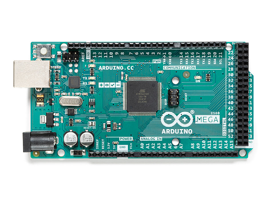
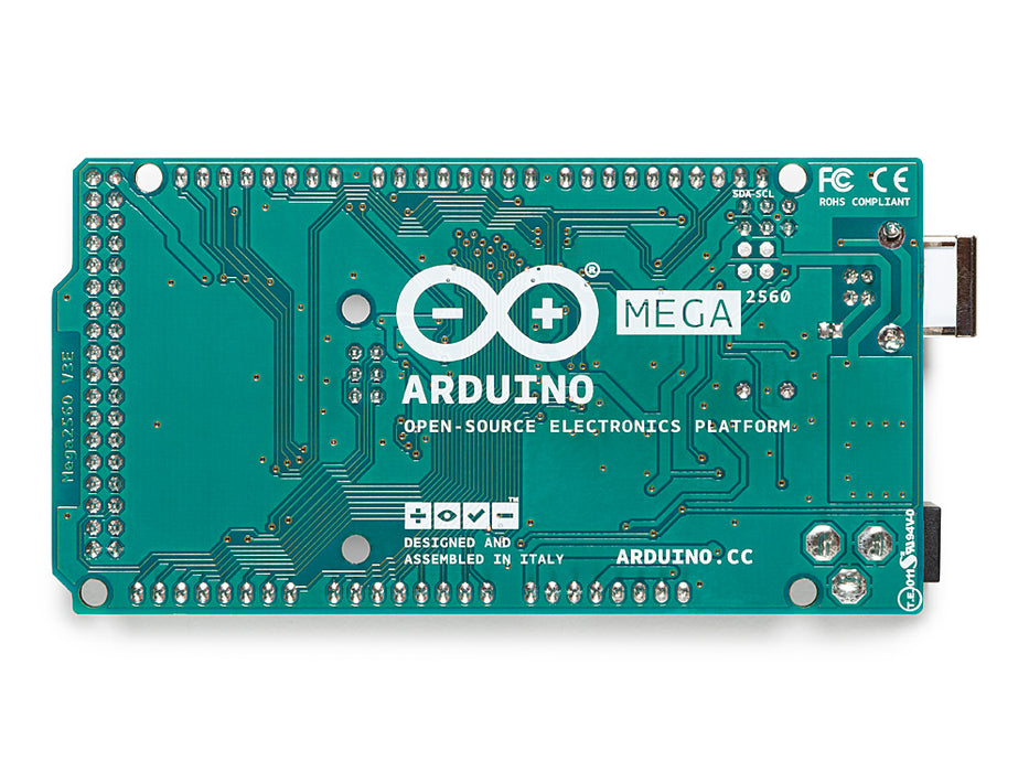
The Arduino Mega 2560 Rev3 is the expanded-I/O workhorse of the classic Arduino lineup. Built around the ATmega2560 microcontroller running at 16 MHz, it provides 54 digital I/O pins, 16 analog input channels, and four independent hardware UART ports — making it the natural choice for projects that push past the limits of the Arduino Uno.
First released in 2010, the Mega 2560 has remained one of the most popular Arduino boards for complex automation, robotics, 3D printer firmware (Marlin), and multi-device communication projects. Its Rev3 revision added the SDA/SCL header pins near the USB connector and the IOREF pin, improving shield compatibility with the Uno R3 standard.
The board is programmed via a Type-B USB port, handled by an ATmega16U2 USB-to-serial bridge, and is fully supported in the Arduino IDE and Arduino Cloud.
Quick Overview
| Property | Value |
|---|---|
| Microcontroller | ATmega2560 (8-bit AVR) |
| Clock Speed | 16 MHz |
| Operating Voltage | 5V |
| Input Voltage (recommended) | 7–12V |
| Digital I/O Pins | 54 (15 with PWM) |
| Analog Input Pins | 16 |
| Flash Memory | 256 KB (8 KB used by bootloader) |
| SRAM | 8 KB |
| EEPROM | 4 KB |
| Hardware UARTs | 4 |
| USB Interface | Type-B (ATmega16U2 bridge) |
| Dimensions | 101.6 × 53.4 mm |
| Weight | 37 g |
Key Features
- 54 digital I/O pins give extensive room for sensors, actuators, and modules
- 15 PWM-capable pins for motor control, LED dimming, and analog-style outputs
- 16 analog input channels (10-bit ADC) for reading a wide range of sensors
- Four hardware UART ports (Serial, Serial1, Serial2, Serial3) enabling simultaneous communication with multiple devices
- ATmega16U2 USB-to-serial bridge for reliable USB programming and serial monitoring
- Fully compatible with a large ecosystem of Arduino Uno shields (same 5V logic, overlapping header footprint)
- Mega-specific shields available for additional modules (displays, motor drivers, etc.)
- ICSP headers for both ATmega2560 and ATmega16U2 for direct in-circuit serial programming
- Power jack accepts 7–12V DC for standalone operation
Technical Specifications
| Specification | Value |
|---|---|
| Microcontroller | ATmega2560 |
| Architecture | 8-bit AVR |
| Clock Speed | 16 MHz |
| Operating Voltage | 5V |
| Recommended Input Voltage | 7–12V |
| Maximum Input Voltage | 6–20V |
| Digital I/O Pins | 54 |
| PWM Pins | 15 (D2–D13, D44–D46) |
| Analog Input Pins | 16 (A0–A15, 10-bit ADC) |
| DC Current per I/O Pin | 40 mA |
| DC Current for 3.3V Pin | 50 mA |
| Flash Memory | 256 KB (8 KB bootloader) |
| SRAM | 8 KB |
| EEPROM | 4 KB |
| Hardware UARTs | 4 (Serial, Serial1, Serial2, Serial3) |
| I2C | 1 (SDA pin 20, SCL pin 21) |
| SPI | 1 (pins 50 MISO, 51 MOSI, 52 SCK, 53 SS; also ICSP header) |
| USB | Type-B (via ATmega16U2) |
| On-Board LED | Pin 13 |
| Dimensions | 101.6 × 53.4 mm |
| Weight | 37 g |
Pinout
Digital I/O Pins
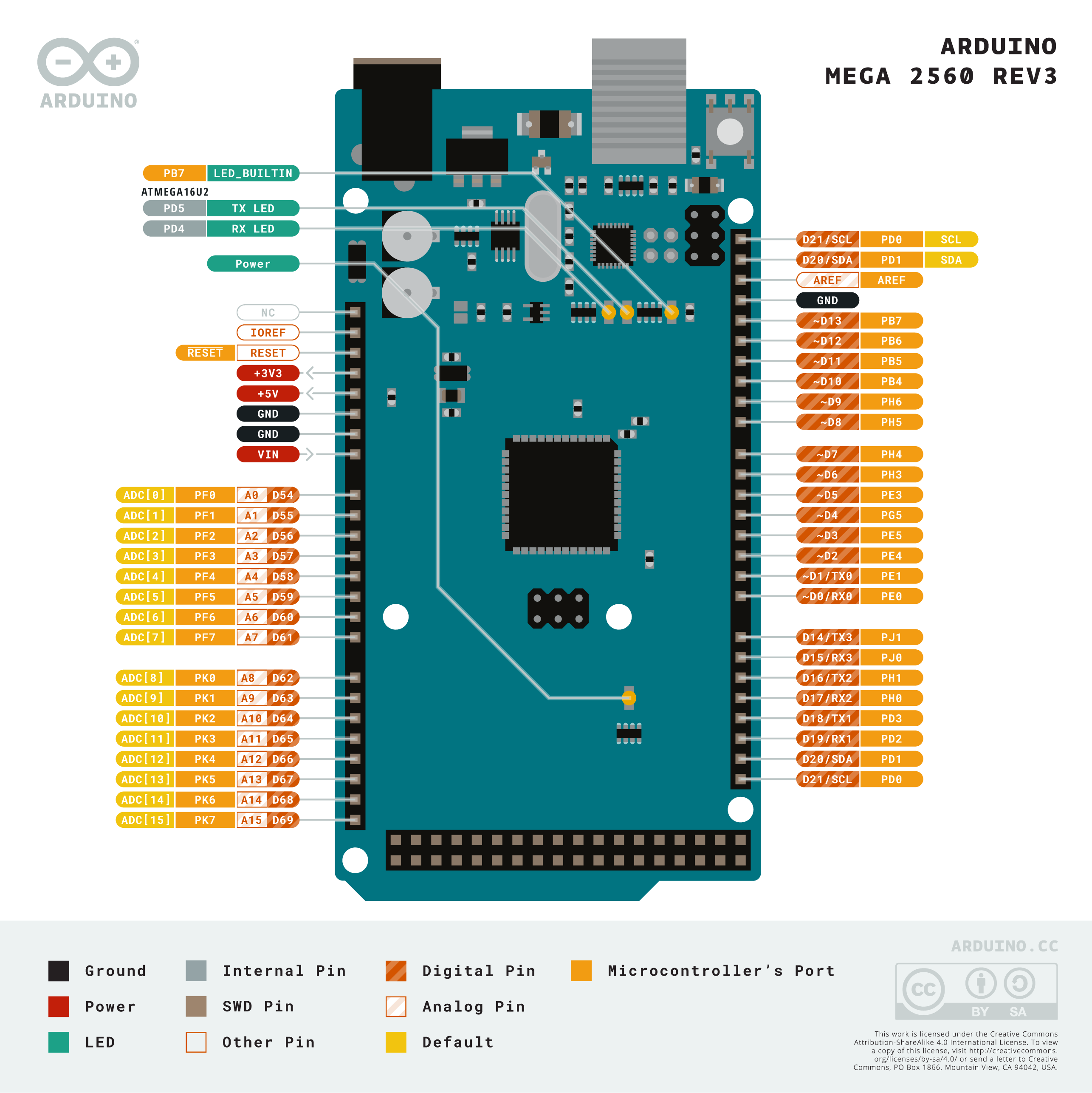
The Mega 2560 provides 54 digital I/O pins, numbered D0–D53. All can be used as general-purpose digital inputs or outputs. 15 of these support PWM output.
| Pin Range | Function |
|---|---|
| D0 (RX0) / D1 (TX0) | Hardware Serial (Serial) — shared with USB bridge |
| D2–D13 | General digital I/O; D3, D5, D6, D9, D10, D11, D13 also PWM |
| D14 (TX3) / D15 (RX3) | Hardware Serial3 |
| D16 (TX2) / D17 (RX2) | Hardware Serial2 |
| D18 (TX1) / D19 (RX1) | Hardware Serial1 |
| D20 (SDA) / D21 (SCL) | I2C bus |
| D22–D53 | General digital I/O; D44, D45, D46 also PWM |
| D50 (MISO) / D51 (MOSI) / D52 (SCK) / D53 (SS) | SPI bus |
Analog Input Pins
| Pin | Notes |
|---|---|
| A0–A15 | 16-channel 10-bit ADC; can also be used as digital I/O |
Power Pins
| Pin | Description |
|---|---|
| VIN | Input voltage (6–20V); same as barrel jack |
| 5V | Regulated 5V output (from USB or VIN) |
| 3.3V | 3.3V output (50 mA max) from on-board regulator |
| GND | Ground |
| RESET | Pull LOW to reset the MCU |
| IOREF | 5V reference for shields |
| AREF | Analog reference voltage for ADC |
Power
The Arduino Mega 2560 Rev3 can be powered in three ways:
- USB: The Type-B USB connector supplies 5V directly from the host. This is sufficient for most development scenarios without external loads.
- DC Barrel Jack: Accepts 7–12V DC (center positive, 2.1 mm). An on-board NCP1117 regulator converts this to 5V.
- VIN Pin: Can accept the same range as the barrel jack when connecting to external supplies on the headers.
The 3.3V pin is regulated to 50 mA maximum — it is not suitable for powering high-current peripherals. Each I/O pin can source or sink up to 40 mA; the total current from all I/O pins combined should not exceed 200 mA.
Getting Started
What You Need
- Arduino Mega 2560 Rev3
- USB Type-A to Type-B cable
- Computer with Arduino IDE installed (download from arduino.cc)
Steps
- Connect the board to your computer using the USB cable.
- Open the Arduino IDE.
- Go to Tools > Board > Arduino AVR Boards > Arduino Mega or Mega 2560.
- Go to Tools > Port and select the COM port for the board.
- Upload the Blink example to confirm everything works.
Blink Example
Multi-Serial Example
The Mega 2560 has four hardware UARTs — a unique advantage over the Uno.
Programming
The Mega 2560 Rev3 is programmed via the Arduino IDE or Arduino CLI. The ATmega16U2 bridge presents the board as a virtual COM port.
- Bootloader: STK500v2 bootloader on the ATmega2560
- Protocol: STK500v2 over USB-serial
- Auto-reset: The IDE triggers a reset via DTR signal before uploading
- ICSP: The 6-pin ICSP header allows burning a new bootloader or programming the MCU directly with AVR-ISP, USBASP, or similar programmers
The ATmega16U2 itself also has an ICSP header for re-flashing its firmware if needed (for DFU mode).
Shield Compatibility
The Mega 2560 Rev3 is largely compatible with Arduino Uno shields because it shares the same 5V logic level and the same header positions for the base connectors. The Rev3 update specifically added the IOREF and SDA/SCL header pins to match the Uno R3 pinout standard.
| Shield Type | Compatibility |
|---|---|
| Arduino Uno R3 shields | Generally compatible (5V logic, same base headers) |
| Arduino Mega-specific shields | Fully compatible (use extended header rows) |
| 3.3V shields | Compatible with level shifting; some work directly via 3.3V pin |
Note that the Mega adds two extra rows of headers beyond the standard Uno connectors. Shields designed specifically for the Mega take advantage of the additional I/O in those rows. Uno shields that use only the shared header rows will work without modification.
Package Contents
| Item | Quantity |
|---|---|
| Arduino Mega 2560 Rev3 board | 1 |
A USB cable is not included. A Type-A to Type-B USB cable is required for programming.
Applications
- Robotics platforms requiring many motor and sensor connections
- 3D printer controller boards running Marlin firmware
- CNC machine controllers (GRBL Mega port)
- Home automation hubs with multiple communication buses
- Multi-sensor data loggers
- Large LED matrix or display controllers
- Industrial prototyping with multiple serial peripherals
- Education and learning platforms for advanced Arduino topics
Where to Buy
- Arduino Official Store — genuine Arduino Mega 2560 Rev3
- Amazon — Arduino and third-party compatible boards
Equivalent Boards
| Board | Key Difference |
|---|---|
| Arduino Due | 32-bit ARM Cortex-M3 at 84 MHz, 3.3V logic, more memory, same Mega form factor |
| Arduino GIGA R1 WiFi | Dual-core 32-bit ARM, built-in wireless, Mega form factor, 3.3V I/O |
| Arduino Uno R3 | Same AVR family, fewer I/O pins (14 digital, 6 analog), simpler projects |
Documentation
Notes
- The Mega 2560 Rev3 replaced the Rev2 with the addition of the IOREF pin and the SDA/SCL header near the USB connector, bringing the pinout up to the Arduino R3 standard.
- The ATmega16U2 USB bridge replaces the older FTDI chip used in earlier Mega boards, eliminating the need for proprietary FTDI drivers on most operating systems.
- Third-party clone boards based on the Mega 2560 are widely available but vary in quality. Official Arduino boards carry the genuine firmware and are manufactured to specification.
- Do not draw more than 40 mA from any single I/O pin or exceed 200 mA total across all I/O pins to avoid damaging the MCU.
Community
- Arduino Forum — official community for questions and projects
- Arduino Discord — real-time chat with the Arduino community
- r/arduino (Reddit) — share projects and ask questions
- Arduino Project Hub — browse community-submitted projects
Revision History
| Version | Date | Notes |
|---|---|---|
| v1.0 | 2026-06 | Initial entry |