
Arduino Nano
Image Gallery
Overview
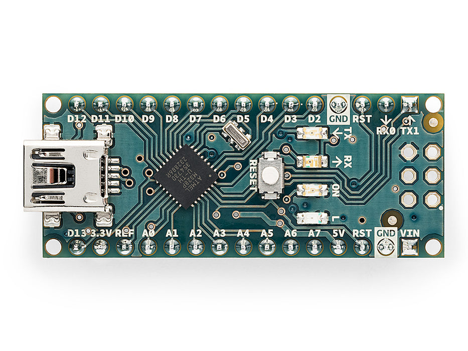
The Arduino Nano is one of the most popular and enduring boards in the Arduino lineup. Introduced in 2008, it packs the same ATmega328P microcontroller found on the Arduino Uno R3 into a compact 18 × 45 mm form factor designed to fit directly into a breadboard. This combination of familiarity and small size has made the Nano a go-to choice for hobbyists, students, and engineers who want to move a project from a full-sized Uno to something more compact without rewriting code.
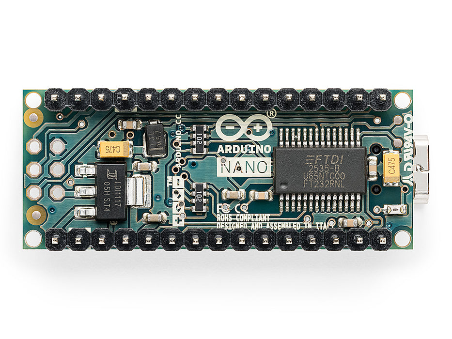
The board connects to a computer via a mini-USB port, which also powers the board. An onboard USB-to-serial bridge chip (FT232RL on original units, CH340 on many modern units and clones) handles communication between the USB port and the ATmega328P's hardware UART. The board runs at 5V logic, making it compatible with the broad ecosystem of 5V sensors and modules.
Because the Nano shares the same microcontroller as the Uno R3, virtually all sketches and libraries that work on the Uno will run unchanged on the Nano. This makes it an ideal choice for finalizing a prototype: develop on the larger Uno, then migrate to the Nano for the finished build.
Quick Overview
| Feature | Detail |
|---|---|
| Microcontroller | ATmega328P (8-bit AVR) |
| Clock Speed | 16 MHz |
| Operating Voltage | 5V |
| Flash Memory | 32 KB (2 KB used by bootloader) |
| SRAM | 2 KB |
| EEPROM | 1 KB |
| Digital I/O Pins | 22 |
| PWM Pins | 6 (D3, D5, D6, D9, D10, D11) |
| Analog Input Pins | 8 (A0–A7) |
| USB Interface | mini-USB (FT232RL or CH340) |
| Dimensions | 18 × 45 mm |
Key Features
- Same ATmega328P MCU as the Arduino Uno R3 — full code and library compatibility
- Compact breadboard-friendly design with 0.1" (2.54 mm) pin spacing
- 32 KB Flash, 2 KB SRAM, 1 KB EEPROM
- 8 analog input channels (A0–A7); note A6 and A7 are analog-only with no digital function
- 6 hardware PWM outputs on D3, D5, D6, D9, D10, and D11
- Hardware I2C on A4 (SDA) and A5 (SCL)
- Hardware SPI on D10 (SS), D11 (MOSI), D12 (MISO), D13 (SCK)
- 1 hardware UART (D0 RX, D1 TX)
- Mini-USB port for power and programming
- Onboard power LED and user-accessible LED on D13
- Operates from 5V USB or 7–12V on VIN pin
Technical Specifications
| Parameter | Value |
|---|---|
| Microcontroller | ATmega328P |
| Architecture | 8-bit AVR |
| Clock Speed | 16 MHz |
| Operating Voltage | 5V |
| Input Voltage (VIN) | 7–12V recommended (max 20V) |
| USB Connector | mini-USB |
| USB-to-Serial Bridge | FT232RL (original) or CH340 (many modern units) |
| Flash Memory | 32 KB (2 KB reserved for bootloader) |
| SRAM | 2 KB |
| EEPROM | 1 KB |
| Digital I/O Pins | 22 |
| PWM Channels | 6 (D3, D5, D6, D9, D10, D11) |
| Analog Input Pins | 8 (A0–A7) |
| ADC Resolution | 10-bit |
| UART | 1 (D0/D1) |
| I2C | 1 (A4 SDA, A5 SCL) |
| SPI | 1 (D10–D13) |
| DC Current per I/O Pin | 40 mA |
| DC Current (3.3V Pin) | 50 mA |
| Board Dimensions | 18 × 45 mm |
| Weight | ~7 g |
Pinout
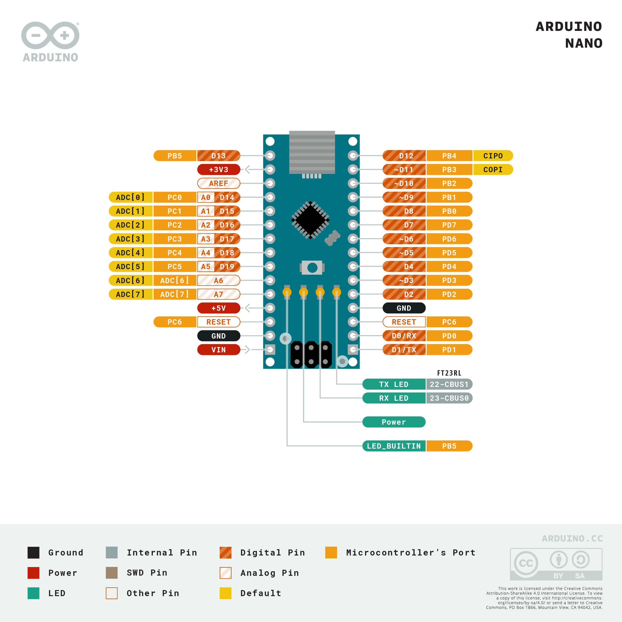
Digital Pins
Pins D0–D13 are digital I/O. D0 (RX) and D1 (TX) are shared with the hardware UART. D13 is connected to the onboard LED.
PWM Pins
D3, D5, D6, D9, D10, and D11 support analogWrite() for PWM output at approximately 490 Hz (D5 and D6 at ~980 Hz).
Analog Pins
A0–A5 are shared analog/digital pins. A6 and A7 are analog input only — they cannot be used as digital I/O.
Communication Pins
| Interface | Pins |
|---|---|
| UART | D0 (RX), D1 (TX) |
| I2C | A4 (SDA), A5 (SCL) |
| SPI | D10 (SS), D11 (MOSI), D12 (MISO), D13 (SCK) |
Power Pins
| Pin | Function |
|---|---|
| VIN | External supply input (7–12V recommended) |
| 5V | Regulated 5V output (from USB or onboard regulator) |
| 3.3V | 3.3V regulated output (up to 50 mA) |
| GND | Ground |
| RESET | Resets the microcontroller when pulled LOW |
| AREF | Analog reference voltage for ADC |
Power
The Arduino Nano can be powered in two ways:
- Via the mini-USB port: the USB 5V rail powers the board directly through a small diode.
- Via the VIN pin: accepts 7–12V (absolute maximum 20V) and steps it down through an onboard voltage regulator to 5V.
When both USB and VIN are connected, VIN takes precedence if it is above the USB voltage. The 3.3V pin provides up to 50 mA from a secondary regulator.
The board does not have an onboard power switch. Current draw is typically 15–20 mA at idle, not counting any attached peripherals or pin outputs.
Getting Started
Install the Arduino IDE
Download and install the Arduino IDE from https://www.arduino.cc/en/software. The Nano appears under Tools > Board > Arduino AVR Boards > Arduino Nano.
Select the Correct Processor
If your Nano uses a CH340 bridge (common on lower-cost units), you may need to install the CH340 driver separately. In the Arduino IDE, under Tools > Processor, select ATmega328P (Old Bootloader) if you encounter upload errors with the default setting.
Blink Example
Read an Analog Sensor
Programming
The Arduino Nano is programmed using the Arduino IDE or any compatible environment (PlatformIO, VS Code with Arduino extension, etc.). Select Arduino Nano under the Arduino AVR Boards package. Sketches are uploaded via the mini-USB port.
The bootloader occupies 2 KB of the 32 KB Flash, leaving 30 KB for user code. The board uses the STK500 protocol for uploads.
Package Contents
| Item | Quantity |
|---|---|
| Arduino Nano board | 1 |
| Mini-USB cable | 1 (included with some retail versions; check listing) |
Applications
- Breadboard prototyping and compact embedded projects
- Sensor data logging (temperature, humidity, soil moisture, etc.)
- Small robotics and motor control
- LED matrix and strip controllers
- Custom keyboards and input devices (with external USB HID libraries)
- Wearables and compact enclosure builds
- Teaching and educational projects
- Replacing larger Uno-based designs in final products
Where to Buy
| Retailer | Link | |
|---|---|---|
| Arduino Official Store | https | //store.arduino.cc/products/arduino-nano |
| Amazon | https | //www.amazon.com/s?k=Arduino+Nano |
Equivalent Boards
| Board | Key Difference |
|---|---|
| Arduino Nano Every | Same form factor, ATmega4809 MCU, more memory (48 KB Flash, 6 KB SRAM), 20 MHz |
| Arduino Uno R3 | Same ATmega328P, larger DIP form factor, Type-B USB |
| Arduino Pro Mini | Same ATmega328P, no onboard USB, even smaller, requires external USB adapter |
Documentation
| Resource | Link | |
|---|---|---|
| Official Product Page | https | //store.arduino.cc/products/arduino-nano |
| Documentation & Pinout | https | //docs.arduino.cc/hardware/nano |
| Arduino IDE Download | https | //www.arduino.cc/en/software |
| ATmega328P Datasheet | https | //ww1.microchip.com/downloads/en/DeviceDoc/Atmel-7810-Automotive-Microcontrollers-ATmega328P_Datasheet.pdf |
Notes
- A6 and A7 are analog-input-only pins. They cannot be used with digitalWrite() or digitalRead().
- Many Nano units sold today use the CH340 USB-to-serial chip rather than the original FT232RL. Windows users may need to install the CH340 driver manually. The board functions identically once the driver is installed.
- When uploading to CH340-based Nanos, select ATmega328P (Old Bootloader) under Tools > Processor if the default setting fails.
- The 3.3V pin is output only (up to 50 mA from the regulator) — do not apply external voltage to it.
- The Nano does not have a built-in voltage regulator indicator; always verify your VIN supply is within range.
- I/O pins operate at 5V logic — compatible with most 5V sensors and modules but not directly compatible with 3.3V-only peripherals without a level shifter.
Community
- Arduino Forum — official community for questions and projects
- Arduino Discord — real-time chat with the Arduino community
- r/arduino (Reddit) — share projects and ask questions
- Arduino Project Hub — browse community-submitted projects
Revision History
| Version | Date | Notes |
|---|---|---|
| v1.0 | 2026-06 | Initial entry |