Arduino Nano RP2040 Connect
Image Gallery
Overview
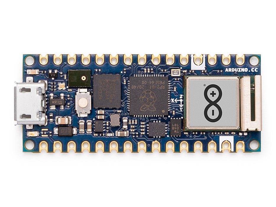
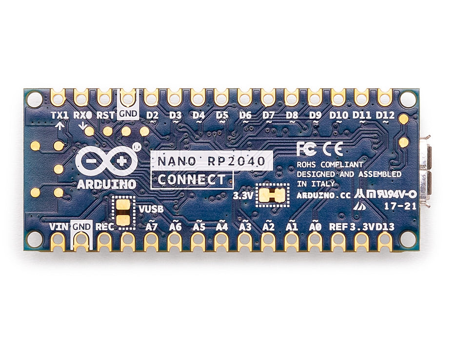
The Arduino Nano RP2040 Connect, released in 2021, is a uniquely positioned board that brings the Raspberry Pi RP2040 microcontroller — best known from the Raspberry Pi Pico — into the Arduino ecosystem, complete with the Nano form factor, wireless connectivity, onboard sensors, and official support for MicroPython and CircuitPython alongside the Arduino IDE.
The RP2040 is a dual-core ARM Cortex-M0+ running at up to 133 MHz with 264 KB of SRAM and access to 16 MB of external QSPI Flash on this board. Its standout feature is the Programmable I/O (PIO) subsystem: eight independent state machines that can implement custom high-speed digital protocols (SPI, I2S, WS2812, etc.) in hardware without using the CPU.
Wireless connectivity comes from the same u-blox NINA-W102 module found on the Nano 33 IoT, providing Wi-Fi 802.11 b/g/n and Bluetooth 4.2 LE. The ATECC608A hardware crypto chip enables secure Arduino IoT Cloud provisioning. Onboard sensors include the LSM6DSOX 6-axis IMU and an MP34DT05 PDM MEMS digital microphone, making the board suitable for TinyML audio and motion applications.
The Nano RP2040 Connect is particularly approachable for Python developers: it can be programmed using MicroPython or CircuitPython by simply copying a .py file to the board over USB, with no IDE setup required.
IMPORTANT: The Nano RP2040 Connect operates at 3.3V logic. I/O pins are NOT 5V tolerant.
Quick Overview
| Feature | Detail | |
|---|---|---|
| Microcontroller | RP2040 (dual-core ARM Cortex-M0+) | |
| Clock Speed | Up to 133 MHz | |
| Operating/Logic Voltage | 3.3V (NOT 5V tolerant) | |
| Flash Memory | 16 MB (QSPI external) | |
| SRAM | 264 KB (on-chip) | |
| Wireless Module | u-blox NINA-W102 (ESP32-based) | |
| Wi-Fi | 802.11 b/g/n (2.4 GHz) | |
| Bluetooth | BLE 4.2 | |
| IMU | LSM6DSOX (6-axis | accelerometer + gyroscope) |
| Microphone | MP34DT05 (PDM MEMS digital) | |
| Crypto | ATECC608A | |
| PIO State Machines | 8 (2 PIO blocks × 4 state machines) | |
| Digital I/O Pins | 22 | |
| Analog Input Pins | 8 | |
| USB Interface | micro-USB | |
| IoT Cloud | Yes (officially supported) | |
| Languages | C/C++ (Arduino IDE), MicroPython, CircuitPython | |
| Dimensions | 18 × 45 mm |
Key Features
- RP2040 dual-core Cortex-M0+ at 133 MHz — the same chip as the Raspberry Pi Pico
- 16 MB QSPI Flash and 264 KB SRAM
- 8 Programmable I/O (PIO) state machines for custom hardware-level protocols
- Wi-Fi 802.11 b/g/n and Bluetooth 4.2 LE via u-blox NINA-W102
- LSM6DSOX 6-axis IMU (accelerometer + gyroscope) onboard
- MP34DT05 PDM MEMS digital microphone for audio capture and TinyML
- ATECC608A hardware crypto for secure IoT Cloud pairing
- Supports Arduino IDE (C/C++), MicroPython, and CircuitPython
- Officially supported on Arduino IoT Cloud
- WiFiNINA library for Wi-Fi from C/C++ sketches
- Pin-compatible with classic Arduino Nano (18 × 45 mm, 0.1" pitch)
- 3.3V logic — compatible with modern low-voltage peripherals
Technical Specifications
| Parameter | Value |
|---|---|
| Microcontroller | RP2040 |
| CPU Cores | 2× ARM Cortex-M0+ |
| Clock Speed | Up to 133 MHz |
| Operating/Logic Voltage | 3.3V |
| Input Voltage (USB) | 5V via micro-USB |
| Input Voltage (VIN) | 4.5–21V |
| USB Connector | micro-USB |
| Flash Memory | 16 MB (QSPI, external) |
| SRAM | 264 KB (on-chip) |
| PIO State Machines | 8 (2 × PIO blocks) |
| Wireless Module | u-blox NINA-W102 (ESP32-based) |
| Wi-Fi | 802.11 b/g/n, 2.4 GHz |
| Bluetooth | BLE 4.2 |
| IMU | LSM6DSOX (3-axis accelerometer, 3-axis gyroscope) |
| Microphone | MP34DT05 (PDM digital MEMS) |
| Crypto Chip | ATECC608A |
| Digital I/O Pins | 22 |
| Analog Input Pins | 8 (A0–A7) |
| ADC Resolution | 12-bit (3 ADC channels on RP2040) |
| UART | 2 |
| I2C | 2 |
| SPI | 2 |
| IoT Cloud | Yes |
| Board Dimensions | 18 × 45 mm |
Pinout
Digital Pins
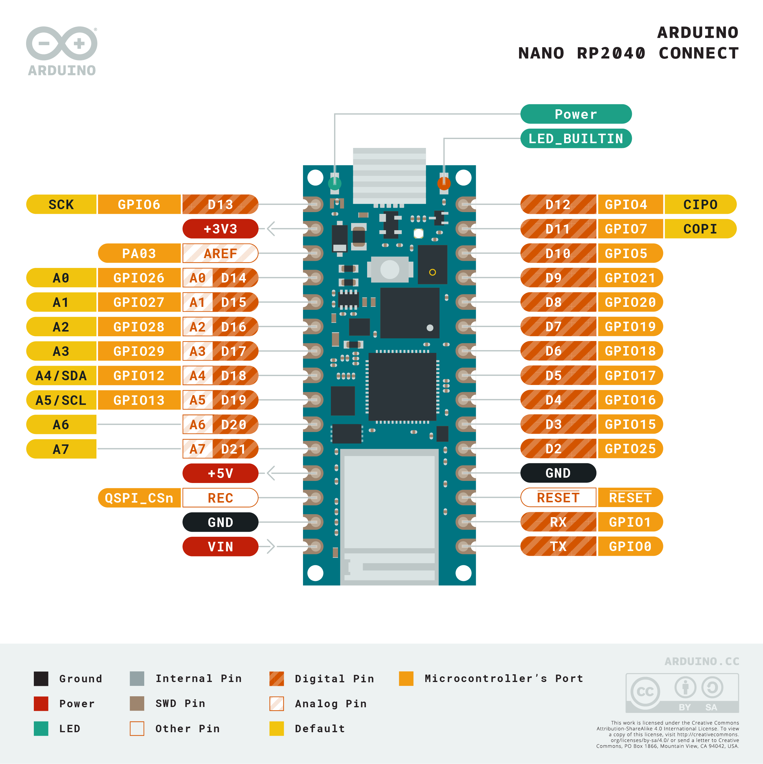
22 digital I/O pins are available in the standard Nano layout. D0 (RX) and D1 (TX) are shared with hardware UART0. D13 is LED_BUILTIN.
Analog Pins
A0–A7 map to analog-capable pins. Note: the RP2040 has only 3 dedicated ADC channels (GPIO26–28). The remaining analog pin mappings may be multiplexed or handled via the Arduino core's pin mapping — refer to the official pinout for accurate ADC assignments.
Communication Pins
| Interface | Pins |
|---|---|
| UART0 | D0 (RX), D1 (TX) |
| I2C0 | A4 (SDA), A5 (SCL) |
| SPI0 | D10 (SS), D11 (MOSI), D12 (MISO), D13 (SCK) |
Power Pins
| Pin | Function |
|---|---|
| VIN | External supply input (4.5–21V) |
| 5V | 5V output from regulator |
| 3.3V | 3.3V regulated output |
| GND | Ground |
| RESET | Resets the microcontroller |
Power
The Nano RP2040 Connect is powered via micro-USB (5V) or the VIN pin (4.5–21V). All logic operates at 3.3V. The NINA-W102 Wi-Fi module can draw up to 200 mA peak during transmissions. Total system current with Wi-Fi active may reach 250 mA or more — use a USB port or power adapter rated for at least 500 mA.
On-Board Components
| Component | Part | Function |
|---|---|---|
| Main MCU | RP2040 | Dual-core Cortex-M0+ application processor |
| Wireless Module | u-blox NINA-W102 | Wi-Fi 802.11 b/g/n + Bluetooth 4.2 LE |
| IMU | LSM6DSOX | 6-axis accelerometer and gyroscope |
| Microphone | MP34DT05 | PDM MEMS digital microphone for audio capture |
| Crypto Chip | ATECC608A | Hardware key storage for secure cloud provisioning |
| Flash | External QSPI | 16 MB program and data storage |
| LED | Onboard | LED on D13 (LED_BUILTIN) |
| RGB LED | Onboard | User-addressable RGB LED |
Microcontroller
The RP2040 is designed by Raspberry Pi Ltd and is distinct from any previous Arduino MCU. Key architectural features:
- Dual Cortex-M0+ cores: the second core can run concurrently (multiprocessing)
- No internal Flash: code executes from the external 16 MB QSPI Flash via XIP (execute-in-place)
- 8 PIO state machines: configurable hardware I/O engines for custom protocols, running independently of the CPU
- USB 1.1 host/device in hardware (used internally)
- 6 independent timer alarms, 4 DMA channels
- 30 GPIO on the RP2040 chip (22 exposed on the Nano footprint)
PIO state machines can implement protocols such as WS2812 LED control, I2S audio, custom UART variants, and stepper motor step/direction — all at precise timing without CPU involvement.
Wireless Connectivity
Wi-Fi 802.11 b/g/n and Bluetooth 4.2 LE are handled by the u-blox NINA-W102 module. The RP2040 communicates with NINA-W102 over an internal SPI interface, controlled via the WiFiNINA library in Arduino C/C++ or via the nina-fw AT-command firmware in MicroPython.
Wi-Fi Example (Arduino C/C++)
IoT Cloud
The Nano RP2040 Connect is officially supported on the Arduino IoT Cloud platform. During provisioning, credentials are stored in the ATECC608A for secure communication. Cloud variables synced over Wi-Fi allow remote monitoring, dashboards, and automations.
Setup steps:
- Create an account at https://cloud.arduino.cc
- Add a new device and select Arduino Nano RP2040 Connect
- Follow the provisioning wizard (requires the Arduino Create Agent on your computer)
- Create IoT Cloud variables and a dashboard panel
Getting Started
Install the Board Package (Arduino IDE)
Open Tools > Board > Boards Manager. Search for "Arduino Mbed OS Nano Boards" and install. Select Arduino Nano RP2040 Connect. Install the WiFiNINA and Arduino_LSM6DSOX libraries.
Blink (Arduino C/C++)
MicroPython Setup
- Download the MicroPython firmware for the Arduino Nano RP2040 Connect from https://micropython.org/download/ARDUINO_NANO_RP2040_CONNECT/
- Hold the BOOTSEL button while plugging in USB — the board mounts as a USB drive.
- Copy the .uf2 firmware file to the drive — it will reboot automatically.
- Use Thonny IDE or rshell to write and upload .py scripts.
Programming
The Nano RP2040 Connect supports three programming environments:
- Arduino IDE (C/C++): Uses the Arduino Mbed OS Nano Boards package. Full access to WiFiNINA, ArduinoBLE, PDM, and sensor libraries.
- MicroPython: Upload .py files over the USB serial interface after flashing MicroPython firmware.
- CircuitPython: Flash CircuitPython firmware from Adafruit; copy .py files to the CIRCUITPY drive.
Arduino C/C++ — Read IMU
MicroPython — Blink and Wi-Fi
Package Contents
| Item | Quantity |
|---|---|
| Arduino Nano RP2040 Connect board | 1 |
| micro-USB cable | 1 (included with some retail versions; check listing) |
Applications
- Wi-Fi and BLE connected IoT sensors and edge nodes
- Audio processing and keyword spotting with onboard PDM microphone
- Motion detection and gesture classification using LSM6DSOX
- TinyML inference on dual-core RP2040 (audio + motion models)
- MicroPython and CircuitPython teaching and education
- Rapid prototyping with Python scripting
- Arduino IoT Cloud monitoring dashboards
- Custom hardware protocols using RP2040 PIO state machines (WS2812, I2S, etc.)
- Robotics and motor control with concurrent dual-core processing
Where to Buy
| Retailer | Link | |
|---|---|---|
| Arduino Official Store | https | //store.arduino.cc/products/arduino-nano-rp2040-connect |
| Amazon | https | //www.amazon.com/s?k=Arduino+Nano+RP2040+Connect |
Equivalent Boards
| Board | Key Difference |
|---|---|
| Arduino Nano 33 IoT | Same NINA-W102 module, SAMD21 MCU (single Cortex-M0+), no microphone, 3.3V |
| Raspberry Pi Pico W | Same RP2040 chip, Wi-Fi via CYW43439 (not NINA-W102), MicroPython, no Arduino Cloud |
| Arduino Nano 33 BLE | nRF52840 ARM M4, BLE only (no Wi-Fi), no microphone, 3.3V |
Documentation
| Resource | Link | |
|---|---|---|
| Official Product Page | https | //store.arduino.cc/products/arduino-nano-rp2040-connect |
| Documentation & Pinout | https | //docs.arduino.cc/hardware/nano-rp2040-connect |
| MicroPython for RP2040 | https | //micropython.org/download/ARDUINO_NANO_RP2040_CONNECT/ |
| WiFiNINA Library | https | //www.arduino.cc/reference/en/libraries/wifinina/ |
| Arduino IoT Cloud | https | //cloud.arduino.cc |
| RP2040 Datasheet | https | //datasheets.raspberrypi.com/rp2040/rp2040-datasheet.pdf |
Notes
- WARNING: The Nano RP2040 Connect operates at 3.3V logic. I/O pins are NOT 5V tolerant. Do not connect 5V signals to any I/O pin without a level shifter.
- The RP2040 has only 3 hardware ADC pins (GPIO26, 27, 28). The Arduino core maps A0–A7 to the Nano footprint, but not all analog pins have true ADC capability on the RP2040. Refer to the official pinout diagram to identify which pins have hardware ADC.
- To enter bootloader mode for firmware flashing (MicroPython/CircuitPython), hold the BOOTSEL button while connecting USB. The board mounts as a USB mass-storage drive.
- If using MicroPython, ensure you use the build specifically compiled for the Arduino Nano RP2040 Connect — it includes the NINA-W102 firmware interface for Wi-Fi.
- The RP2040's PIO state machines are a powerful but low-level feature. The Arduino_MachineControl and other community libraries provide high-level wrappers for common PIO use cases.
- The onboard microphone (MP34DT05) outputs PDM audio. In Arduino C/C++ use the PDM library. In MicroPython/CircuitPython, access depends on the specific firmware version.
Community
- Arduino Forum — official community for questions and projects
- Arduino Discord — real-time chat with the Arduino community
- r/arduino (Reddit) — share projects and ask questions
- Arduino Project Hub — browse community-submitted projects
Revision History
| Version | Date | Notes |
|---|---|---|
| v1.0 | 2026-06 | Initial entry |