Arduino Portenta H7
Image Gallery
Overview
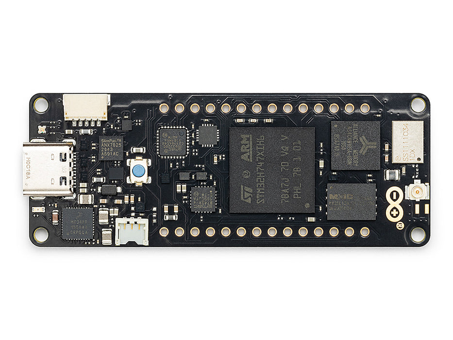
The Arduino Portenta H7 is a professional-grade, dual-core microcontroller board aimed at industrial, AI, and machine vision applications. At its heart is the STM32H747XI, which combines an ARM Cortex-M7 running at 480 MHz and a Cortex-M4 running at 240 MHz. Both cores can be programmed independently — the M7 typically handles the main application while the M4 handles real-time tasks or offloaded processing.
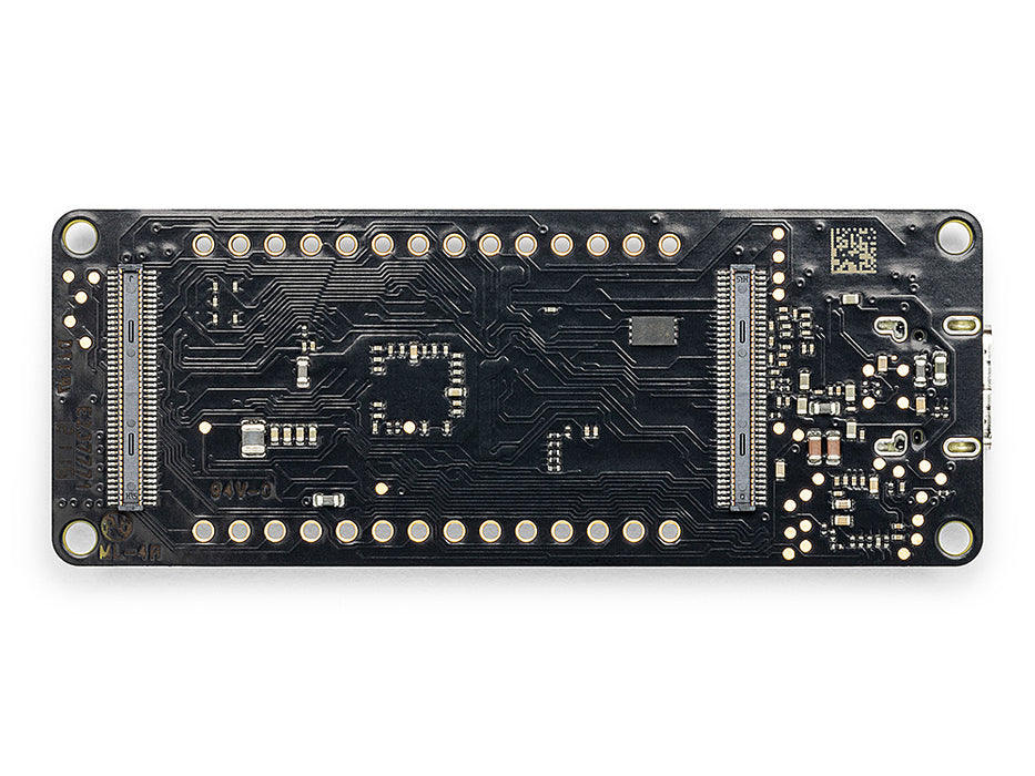
Released in 2020, the Portenta H7 was Arduino's first board targeting the professional and industrial market segment. It introduced the high-density connector standard — two 80-pin connectors on the bottom of the board — which allows it to slot into a wide range of carrier boards and shields, including the Portenta Hat Carrier, Portenta Max Carrier, Portenta Breakout, and various Vision Shields.
The board supports multiple programming environments: the Arduino framework (for both cores), MicroPython, OpenMV (for machine vision and ML inference), and JavaScript via Espruino. This flexibility makes it suitable for rapid prototyping through to production deployment.
Quick Overview
| Property | Value |
|---|---|
| MCU | STM32H747XI (Cortex-M7 @ 480 MHz + Cortex-M4 @ 240 MHz) |
| SRAM | 1 MB internal + 8 MB external SDRAM |
| Flash | 2 MB internal + 16 MB external QSPI |
| Wireless | Wi-Fi 802.11 b/g/n + Bluetooth 5.0 |
| USB | USB-C (USB OTG HS 480 Mbit/s) |
| Video Output | 2 × micro-HDMI (up to 1080p60) |
| Camera | MIPI CSI connector |
| I/O Connectors | 2 × 80-pin high-density connectors |
| Operating Voltage | 3.3V |
| Input Voltage | 5V via USB-C or external |
| SKU | ABX00042 |
Key Features
- Dual-core STM32H747XI: Cortex-M7 at 480 MHz and Cortex-M4 at 240 MHz, both independently programmable
- 1 MB internal SRAM plus 8 MB external SDRAM for memory-intensive workloads
- 2 MB internal Flash plus 16 MB external QSPI Flash for program and data storage
- Murata 1DX module providing Wi-Fi 802.11 b/g/n and Bluetooth 5.0 in a single chip
- USB-C with native USB OTG High-Speed at 480 Mbit/s
- Dual micro-HDMI ports supporting video output up to 1080p at 60 fps via MIPI DSI
- MIPI CSI camera interface for direct camera module attachment
- Two 80-pin high-density connectors enabling modular expansion with carrier boards
- Compatible with Portenta Hat Carrier, Max Carrier, Vision Shield, and Breakout boards
- Supports Arduino framework, MicroPython, OpenMV (for ML vision), and JavaScript (Espruino)
- Designed for AI and machine learning on the edge
- Industrial and professional application tier
Technical Specifications
| Parameter | Value |
|---|---|
| Microcontroller | STM32H747XI |
| Core Architecture | ARM Cortex-M7 + ARM Cortex-M4 (dual-core) |
| M7 Clock Speed | 480 MHz |
| M4 Clock Speed | 240 MHz |
| Internal SRAM | 1 MB |
| External SDRAM | 8 MB (QSPI) |
| Internal Flash | 2 MB |
| External QSPI Flash | 16 MB |
| Wireless Module | Murata 1DX |
| Wi-Fi Standard | 802.11 b/g/n (2.4 GHz) |
| Bluetooth | 5.0 |
| USB | USB-C, USB OTG HS (480 Mbit/s) |
| Video Output | 2 × micro-HDMI (MIPI DSI, up to 1080p60) |
| Camera Interface | MIPI CSI |
| I/O Connectors | 2 × 80-pin high-density (bottom) |
| Operating Voltage | 3.3V (some pins 5V tolerant — check datasheet) |
| Input Voltage | 5V via USB-C or external supply |
| ADC Resolution | Up to 16-bit |
| PWM | Yes (multiple channels) |
| Dimensions | 66.04 × 25.4 mm |
Pinout
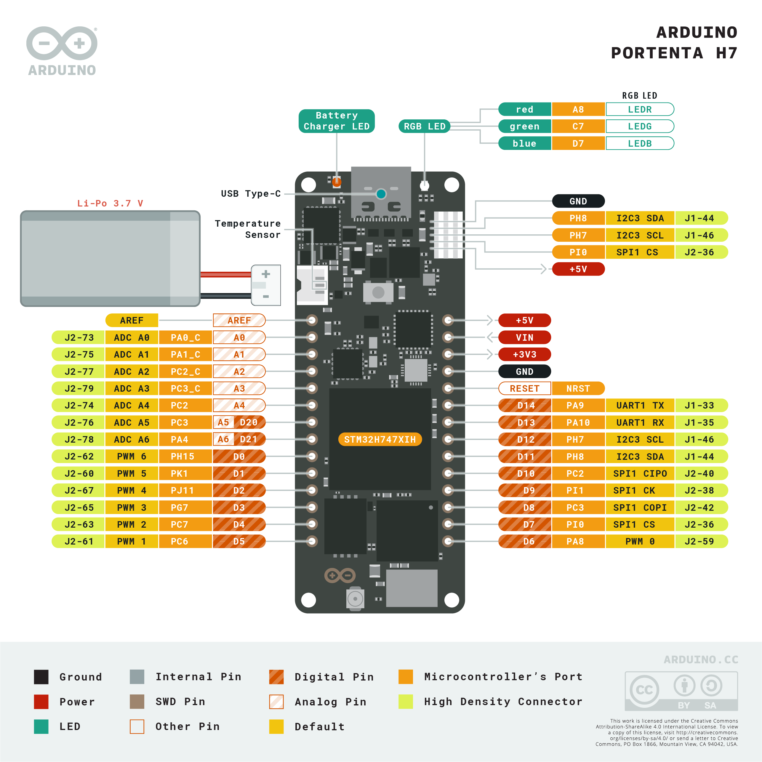
The Portenta H7 exposes its I/O via two 80-pin high-density connectors on the bottom of the board (J1 and J2). When used standalone, a Portenta Breakout board is required to access individual pins. When mounted on a carrier board, the carrier routes the signals to accessible headers or terminal blocks.
Key signal groups available on the high-density connectors:
| Signal Group | Description |
|---|---|
| Digital I/O | Multiple GPIO pins at 3.3V logic |
| Analog Inputs | 12-bit and 16-bit ADC channels |
| PWM | Multiple PWM-capable pins |
| UART | Multiple UART interfaces |
| SPI | SPI bus |
| I2C | I2C bus |
| CAN | CAN bus interface |
| USB | USB OTG HS differential pair |
| MIPI DSI | 4-lane display interface (drives micro-HDMI outputs) |
| MIPI CSI | Camera serial interface |
| SDIO | SD card interface |
| Ethernet | 10/100 Mbps Ethernet (via carrier board) |
High-Density Connector Notes
The two 80-pin connectors (J1 and J2) are board-to-board connectors. They require a mating carrier board or the Portenta Breakout board for access. Always verify 3.3V logic compatibility before connecting external peripherals.
Power
| Power Parameter | Value |
|---|---|
| Input Voltage (USB) | 5V via USB-C |
| Input Voltage (External) | 5V via high-density connector VIN pin |
| Operating Voltage (I/O) | 3.3V |
| 5V Tolerance | Some pins only — refer to official datasheet |
| Battery Support | Via carrier board (e.g., Portenta Hat Carrier) |
| Power Consumption | Varies by core activity and wireless use |
The Portenta H7 operates at 3.3V I/O. Some pins may be 5V tolerant, but this must be verified in the official STM32H747 datasheet before connecting 5V peripherals. Do not assume 5V tolerance across all pins.
On-Board Components
| Component | Part | Function |
|---|---|---|
| Microcontroller | STM32H747XI | Dual-core M7 + M4 application processor |
| Wireless Module | Murata 1DX | Wi-Fi 802.11 b/g/n + Bluetooth 5.0 |
| External SDRAM | 8 MB | Extended RAM via QSPI |
| External Flash | 16 MB | Extended program/data storage via QSPI |
| USB Controller | Built into STM32H747 | USB OTG HS 480 Mbit/s |
| Video Bridge | On-board MIPI DSI to HDMI | Drives 2 × micro-HDMI outputs |
| Camera Connector | MIPI CSI | Direct camera attachment |
| High-Density Connectors | 2 × 80-pin | Carrier board interface (J1 and J2) |
| Power LED | On-board | Power indicator |
| User LED | On-board (RGB) | Programmable status LED |
Microcontroller
The STM32H747XI from STMicroelectronics is an asymmetric dual-core microcontroller from the STM32H7 series. The two cores share peripherals and memory but operate independently.
| Core | Details |
|---|---|
| Cortex-M7 | 480 MHz, FPU, DSP instructions, primary application core |
| Cortex-M4 | 240 MHz, FPU, DSP instructions, secondary/real-time core |
Both cores can access the peripherals, with hardware semaphores and mailboxes used for inter-core communication. In the Arduino environment, the M7 core runs the main sketch by default. The M4 can be programmed separately via the Arduino IDE by selecting the Portenta H7 (M4 core) target.
The STM32H747XI includes hardware floating-point units on both cores, making it capable of signal processing and lightweight ML inference without an external coprocessor.
Wireless Connectivity
The Murata 1DX module integrates Wi-Fi and Bluetooth in a compact package certified for multiple regions.
| Wireless Feature | Value |
|---|---|
| Module | Murata 1DX |
| Wi-Fi | 802.11 b/g/n (2.4 GHz) |
| Bluetooth | 5.0 (Classic + LE) |
| Antenna | On-board PCB antenna |
| Certification | CE, FCC, IC (regional certifications) |
| Arduino Library | WiFi (built into Arduino Mbed OS Portenta core) |
Getting Started
Prerequisites
- Arduino IDE 2.x (recommended) or Arduino IDE 1.8.19+
- Install the Arduino Mbed OS Portenta Boards package via Boards Manager
- USB-C cable (data-capable, not charge-only)
- Optional: Portenta Breakout board for pin access
Board Setup
- Open Arduino IDE
- Go to Tools > Board > Boards Manager
- Search for "Arduino Mbed OS Portenta Boards" and install
- Select Tools > Board > Arduino Portenta H7 (M7 core)
- Connect the Portenta H7 via USB-C
- Select the correct port under Tools > Port
Blink Example (M7 Core)
Wi-Fi Connection Example
Programming
The Portenta H7 supports several programming environments:
| Environment | Details |
|---|---|
| Arduino IDE | Full Arduino framework support for M7 and M4 cores separately |
| Arduino Pro IDE | Advanced IDE with OpenMV integration for ML vision workflows |
| MicroPython | Flash MicroPython firmware to run Python scripts on M7 |
| OpenMV | Machine vision framework — camera processing, object detection, QR codes |
| Espruino | JavaScript runtime for the Portenta H7 |
Dual-Core Programming
In Arduino IDE, you can select either the M7 or M4 core as the programming target. The M7 sketch runs as the main application. The M4 sketch is embedded within the M7 firmware and launched by the M7 at startup using the BootM4() call.
Package Contents
| Item | Quantity |
|---|---|
| Arduino Portenta H7 board | 1 |
A USB-C cable and carrier board are sold separately. A Portenta Breakout board is recommended for prototyping.
Applications
- Industrial edge computing and IIoT gateways
- Machine vision and AI inference (with Vision Shield or MIPI CSI camera)
- Robotics and motion control (dual-core enables real-time + application layers)
- Predictive maintenance and vibration analysis
- High-speed data acquisition
- Smart building automation
- Audio processing and voice recognition
- Fleet and asset tracking with wireless connectivity
- Digital signage (dual micro-HDMI outputs)
- Production-grade IoT devices requiring wireless + compute
Where to Buy
- Arduino Official Store — official source
- Amazon — search for Arduino Portenta H7
Equivalent Boards
| Board | MCU | Key Difference |
|---|---|---|
| Arduino Portenta C33 | Renesas R7FA6M5 (Cortex-M33, 200 MHz) | Lower cost, single-core, same form factor |
| Arduino Portenta X8 | NXP i.MX 8M Mini (A53) + STM32H747 (M7+M4) | Linux-capable, more powerful, higher cost |
| Arduino GIGA R1 WiFi | STM32H747XI (same MCU) | Arduino Mega form factor, no high-density connectors |
Documentation
Notes
- All I/O on the Portenta H7 operates at 3.3V logic. Connecting 5V signals directly to I/O pins may damage the board. Always verify 5V tolerance in the STM32H747XI datasheet for specific pins before use.
- The high-density connectors are not breadboard-compatible. A Portenta Breakout board or a compatible carrier board is required for prototyping.
- The M4 core must be started programmatically by the M7 core using BootM4(). It is not automatically activated at power-on.
- When flashing MicroPython or OpenMV firmware, the board will no longer run Arduino sketches until Arduino firmware is reflashed.
- USB-C cables must support data transfer. Charge-only USB-C cables will not allow programming.
Community
- Arduino Forum — official community
- Arduino Discord — real-time chat
- r/arduino (Reddit) — community
- Arduino Project Hub — projects
Revision History
| Version | Date | Notes |
|---|---|---|
| v1.0 | 2026-06 | Initial entry |