
Arduino UNO R3
Image Gallery
Overview
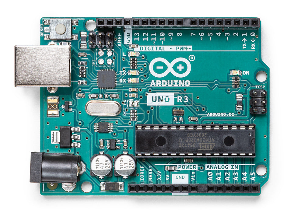
The UNO R3 was designed to be the most accessible entry point to electronics prototyping. It runs at 5 V logic, making it directly compatible with thousands of sensors, modules, and shields produced over the past fifteen years. The ATmega328P is a mature, well-documented 8-bit AVR processor with a predictable, deterministic execution model that suits beginners learning about timing and hardware control.
USB connectivity is provided through a second microcontroller, an ATmega16U2, which acts as a USB-to-serial bridge between the host computer and the ATmega328P's hardware UART. This means the board appears as a virtual COM port and does not support native USB HID without custom firmware on the ATmega16U2.
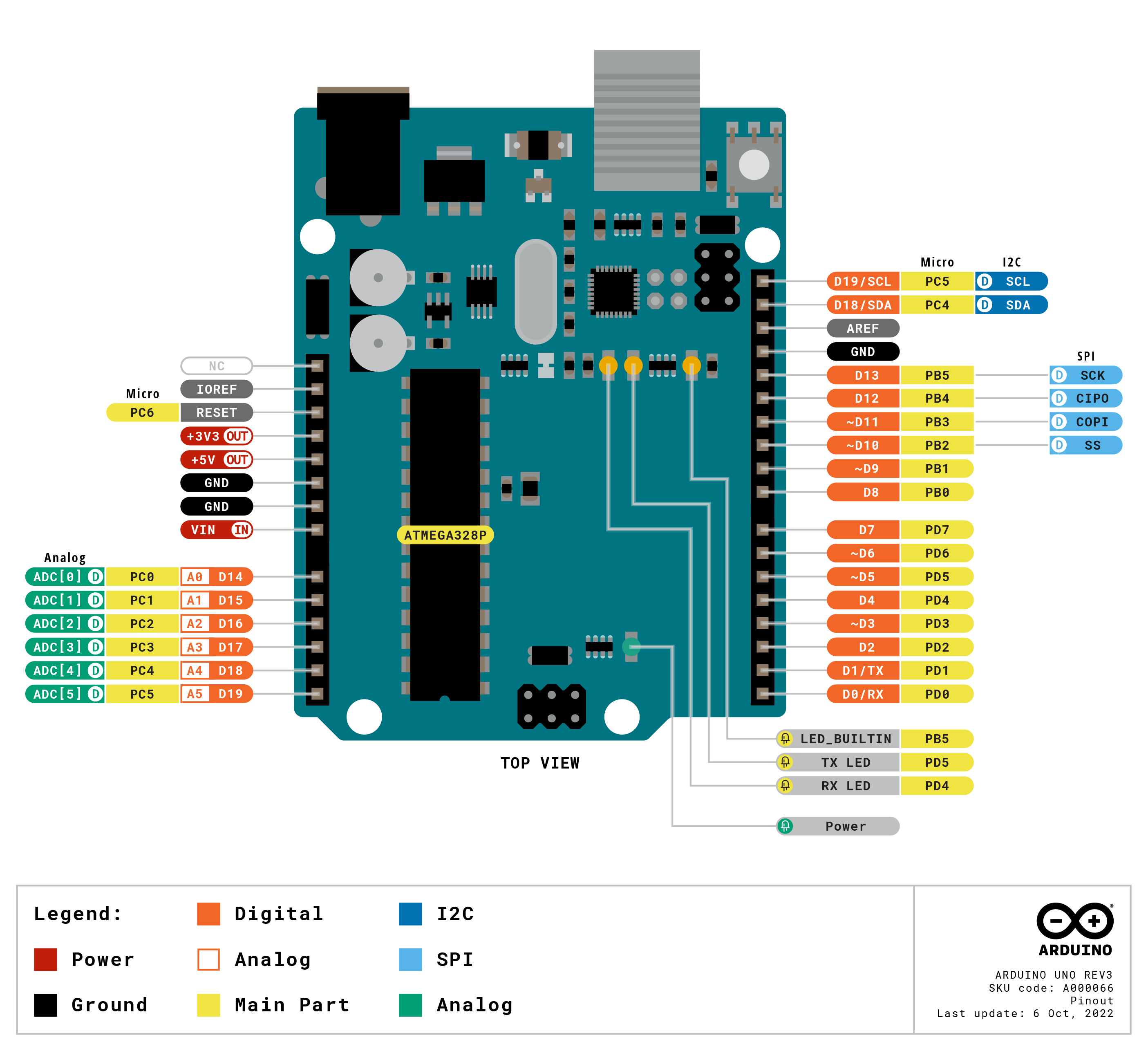
The R3 revision added the SDA/SCL pins in a dedicated header position above the AREF pin (in addition to their shared positions on A4/A5), a second IOREF pin allowing shields to detect operating voltage, and a reset pin on the ICSP header. These additions formed what became known as the "R3" header standard, adopted by later Arduino boards.
Despite the release of more powerful successors such as the UNO R4 Minima and UNO R4 WiFi, the UNO R3 remains in active production because of its unmatched library support, shield compatibility, and simplicity.
Quick Overview
| Feature | Detail |
|---|---|
| MCU | ATmega328P, 8-bit AVR, 16 MHz |
| Flash | 32 KB (0.5 KB used by bootloader) |
| SRAM | 2 KB |
| EEPROM | 1 KB |
| Operating Voltage | 5 V |
| USB | Type-B (ATmega16U2 USB-to-serial) |
| Digital I/O | 14 pins |
| PWM Outputs | 6 (D3, D5, D6, D9, D10, D11) |
| Analog Inputs | 6 (10-bit ADC, A0–A5) |
| Form Factor | Arduino Uno |
| Dimensions | 68.6 × 53.4 mm |
| Weight | 25 g |
Key Features
- ATmega328P microcontroller — robust, thoroughly documented, enormous community support
- 5 V operating voltage — compatible with virtually all legacy sensors and modules
- 32 KB Flash, 2 KB SRAM, 1 KB EEPROM
- 14 digital I/O pins with 6 capable of PWM output
- 6 analog input pins with 10-bit ADC (returns 0–1023)
- Dedicated SDA/SCL header pins (R3 standard) plus shared positions on A4/A5
- ICSP header for direct SPI access and bootloader burning
- ATmega16U2 USB-to-serial bridge — reliable virtual COM port on any host OS
- IOREF pin allows shields to automatically detect board logic voltage
- Maximum shield and library compatibility of any Arduino board
- Programmable via Arduino IDE 1.x or 2.x — no additional board packages needed (installed by default)
- 40 mA per I/O pin — can directly drive LEDs without current-limiting resistors in many cases
Technical Specifications
| Parameter | Value |
|---|---|
| Microcontroller | ATmega328P (8-bit AVR) |
| Clock Speed | 16 MHz |
| Flash Memory | 32 KB (0.5 KB bootloader) |
| SRAM | 2 KB |
| EEPROM | 1 KB |
| Operating Voltage | 5 V |
| Input Voltage (Recommended) | 7–12 V via VIN / barrel jack |
| Input Voltage (Maximum) | 6–20 V |
| Digital I/O Pins | 14 |
| PWM Pins | 6 (D3, D5, D6, D9, D10, D11) |
| Analog Input Pins | 6 (A0–A5) |
| ADC Resolution | 10-bit (0–1023) |
| DAC | None |
| DC Current per I/O Pin | 40 mA |
| DC Current for 3.3 V Pin | 50 mA |
| USB Connector | Type-B |
| USB Interface | ATmega16U2 USB-to-serial bridge (virtual COM port) |
| Native USB HID | No |
| UART | 1 (D0/D1) |
| I2C | 1 (A4 = SDA, A5 = SCL; also dedicated R3 header) |
| SPI | 1 (D10–D13 and ICSP header) |
| RTC | None |
| DAC | None |
| CAN Bus | None |
| Wireless | None |
| Dimensions | 68.6 × 53.4 mm |
| Weight | 25 g |
Pinout
Digital Pins (D0–D13)
| Pin | Function | Notes |
|---|---|---|
| D0 | RX (UART) | Serial receive — shared with USB bridge |
| D1 | TX (UART) | Serial transmit — shared with USB bridge |
| D2 | Digital I/O | External interrupt (INT0) |
| D3 | Digital I/O / PWM | External interrupt (INT1), Timer2 PWM |
| D4 | Digital I/O | General purpose |
| D5 | Digital I/O / PWM | Timer0 PWM |
| D6 | Digital I/O / PWM | Timer0 PWM |
| D7 | Digital I/O | General purpose |
| D8 | Digital I/O | General purpose |
| D9 | Digital I/O / PWM | Timer1 PWM |
| D10 | Digital I/O / PWM / SS | SPI chip select, Timer1 PWM |
| D11 | Digital I/O / PWM / MOSI | SPI MOSI, Timer2 PWM |
| D12 | Digital I/O / MISO | SPI MISO |
| D13 | Digital I/O / SCK / LED | SPI clock, onboard LED |
Analog Pins (A0–A5)
| Pin | Function | Notes |
|---|---|---|
| A0 | Analog Input | 10-bit ADC |
| A1 | Analog Input | 10-bit ADC |
| A2 | Analog Input | 10-bit ADC |
| A3 | Analog Input | 10-bit ADC |
| A4 | Analog Input / SDA | I2C data (also usable as digital I/O) |
| A5 | Analog Input / SCL | I2C clock (also usable as digital I/O) |
Power and Other Pins
| Pin | Function |
|---|---|
| VIN | Unregulated input (7–12 V recommended, 6–20 V max) |
| 5V | Regulated 5 V output |
| 3V3 | 3.3 V regulated output (50 mA max) |
| GND | Ground (multiple pins) |
| RESET | Pull LOW to reset MCU |
| IOREF | Voltage reference for shields (5 V on R3) |
| AREF | Analog reference voltage for ADC |
| SDA | I2C data (dedicated R3 header, same as A4) |
| SCL | I2C clock (dedicated R3 header, same as A5) |
Power
The UNO R3 can be powered three ways:
- USB Type-B: Connect to a computer or USB power supply. Provides regulated 5 V directly to the board. Best for development and desktop applications.
- Barrel Jack / VIN: A centre-positive 2.1 mm barrel jack accepts 7–12 V DC (6–20 V absolute limits). The on-board regulator converts it to 5 V. Use this for standalone, battery, or wall-adapter-powered projects.
- 5V Pin: A regulated 5 V supply applied directly to the 5V pin bypasses the on-board regulator. Use only with an accurately regulated source.
The ATmega328P can source or sink up to 40 mA per I/O pin, with a total package limit. Do not draw excessive total current from the 5 V rail — leave headroom for shields and sensors.
Getting Started
Step 1 — Install the Arduino IDE
Download Arduino IDE 2 from https://www.arduino.cc/en/software. The UNO R3 board package is pre-installed.
Step 2 — Connect and Select Board
Connect the UNO R3 via USB Type-B cable. In the IDE, choose Tools > Board > Arduino AVR Boards > Arduino Uno, then select the correct COM port under Tools > Port.
Step 3 — Upload Blink
Upload the sketch. The onboard LED on D13 will blink once per second.
Step 4 — Open the Serial Monitor
Open Tools > Serial Monitor, set baud to 9600, and watch the output.
Programming
The UNO R3 is one of the best-supported boards in the Arduino ecosystem. It uses the standard Arduino AVR Boards package (built into the IDE). All standard Arduino functions are supported:
- pinMode(), digitalWrite(), digitalRead()
- analogRead() (10-bit, returns 0–1023)
- analogWrite() (8-bit PWM on D3, D5, D6, D9, D10, D11)
- Serial, Wire (I2C), SPI
- tone(), pulseIn(), shiftOut()
The ATmega328P has no floating-point hardware; floating-point operations are handled in software and are slower than on 32-bit ARM boards.
Reading an Analog Sensor
Shield Compatibility
The UNO R3 defines the standard Arduino Uno shield form factor. Any shield labelled "Arduino Uno compatible" is designed to work with this board. Examples include:
- Motor driver shields (L293D, TB6612FNG, L298N)
- Ethernet and Wi-Fi shields
- LCD and display shields
- Sensor and proto shields
- Data logging and SD card shields
- Relay shields
The R3 header standard (dedicated SDA/SCL pins and IOREF pin) ensures compatibility with shields designed for R3 and later boards. The UNO R3 is the gold standard for shield compatibility.
Package Contents
| Item | Quantity |
|---|---|
| Arduino UNO R3 board | 1 |
| USB Type-B cable | 1 (included in some bundles — verify at purchase) |
Applications
- Electronics education and learning to program microcontrollers
- Prototyping sensor systems, data loggers, and display projects
- Home automation with relay shields and radio modules
- Robotics — motor control, servo positioning, line following
- Art installations and interactive displays
- DIY weather stations and environmental monitors
- Simple MIDI controllers and music gadgets
- Industrial prototyping where 5 V compatibility is required
- Basis for custom shield development
Where to Buy
| Retailer | Link | |
|---|---|---|
| Arduino Official Store | https | //store.arduino.cc/products/arduino-uno-rev3 |
| Amazon | https | //www.amazon.com/s?k=Arduino+Uno+R3 |
Equivalent Boards
| Board | Key Difference |
|---|---|
| Arduino UNO R4 Minima | Same Uno form factor, 32-bit ARM RA4M1 at 48 MHz, USB-C, 256 KB Flash, 32 KB SRAM, DAC, RTC, CAN FD — more powerful successor |
| Arduino UNO R4 WiFi | Same as R4 Minima plus Wi-Fi, BLE, and 12×8 LED matrix |
| Arduino Nano | Same ATmega328P at 16 MHz in a smaller breadboard-friendly form factor — not shield compatible |
| Arduino Mega 2560 | ATmega2560, more I/O pins (54 digital, 16 analog), more memory — same AVR family, larger form factor |
Documentation
| Resource | URL | |
|---|---|---|
| Official Product Page | https | //docs.arduino.cc/hardware/uno-rev3 |
| Arduino Store | https | //store.arduino.cc/products/arduino-uno-rev3 |
Notes
- The ATmega16U2 USB-to-serial chip can be reprogrammed with custom firmware using the ICSP header and DFU mode, but this is an advanced operation.
- The D0 (RX) and D1 (TX) pins are shared with the USB-to-serial bridge. Avoid using these pins for external sensors while the USB connection is active.
- The 10-bit ADC returns values 0–1023. For higher-resolution analog measurement, consider the UNO R4 Minima (12-bit ADC).
- EEPROM data persists through power cycles and program uploads. The EEPROM.h library provides read/write access.
- The ATmega328P has no native USB HID capability. The board cannot emulate a keyboard or mouse without custom ATmega16U2 firmware.
- Total current draw from the 5V regulator (when powered via VIN/barrel jack) should be kept below 800 mA for the on-board regulator's thermal limits.
Community
- Arduino Forum — official community for questions and projects
- Arduino Discord — real-time chat with the Arduino community
- r/arduino (Reddit) — share projects and ask questions
- Arduino Project Hub — browse community-submitted projects
Revision History
| Version | Date | Notes |
|---|---|---|
| v1.0 | 2026-06 | Initial entry |