
Arduino UNO R4 Minima
Image Gallery
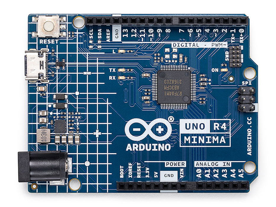

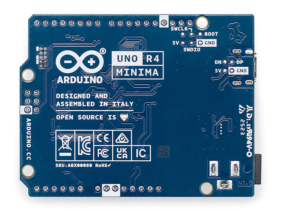
Overview
The UNO R4 Minima builds on more than a decade of UNO heritage. Its predecessor, the UNO R3, used an 8-bit ATmega328P at 16 MHz with 2 KB of SRAM — constraints that limited real-world applications. The RA4M1 on the R4 Minima offers 16× more SRAM, 8× more Flash, a hardware FPU for floating-point math, and a 12-bit ADC for higher-resolution analog measurements. The board retains 5 V logic and the standard Uno header layout, so the vast majority of Uno shields plug straight in.
Key additions over the UNO R3 include a CAN FD peripheral for automotive and industrial bus communication, a 12-bit DAC on pin A0 for generating analog voltage waveforms, an on-board op-amp for signal conditioning, an RTC with an external battery-backup pin (VRTC) that keeps time running when board power is removed, and a USB-C port with native USB HID support. A dedicated OFF pin lets firmware cut power to the board programmatically.
The only features not present versus the UNO R4 WiFi are the ESP32-S3 co-processor (Wi-Fi / Bluetooth), the 12×8 red LED matrix, and the Qwiic I2C connector — the trade-off for a lower retail price.
Quick Overview
| Feature | Detail |
|---|---|
| MCU | Renesas RA4M1, ARM Cortex-M4 with FPU, 48 MHz |
| Flash | 256 KB |
| SRAM | 32 KB |
| Operating Voltage | 5 V |
| USB | USB-C (native HID) |
| Digital I/O | 14 pins |
| PWM Outputs | 6 (D3, D5, D6, D9, D10, D11) |
| Analog Inputs | 6 (12-bit ADC, A0–A5) |
| DAC | 1 × 12-bit (A0) |
| RTC | Built-in, VRTC pin for battery backup |
| CAN Bus | CAN FD (requires external transceiver) |
| Form Factor | Arduino Uno |
| Dimensions | 68.85 × 53.34 mm |
Key Features
- 32-bit ARM Cortex-M4 with hardware FPU at 48 MHz
- 256 KB Flash and 32 KB SRAM — a dramatic step up from the UNO R3
- 12-bit ADC on all six analog inputs (A0–A5) for higher measurement precision
- 12-bit DAC on pin A0 for true analog voltage output
- Built-in RTC with VRTC pin — connect a CR2032 coin cell to maintain time during power-off
- Built-in operational amplifier (A1 = non-inverting input, A2 = inverting input, A3 = output)
- CAN FD bus support on D4 (CANRX0) and D5 (CANTX0) — requires an external transceiver such as the TJA1050
- Native USB HID via USB-C — emulate keyboard, mouse, or gamepad with the Arduino Keyboard / Mouse libraries
- OFF pin: drive HIGH to cut power to the board from firmware
- Full backwards-compatible Uno header footprint for shield support
- 5 V logic — compatible with the majority of existing Uno shields and sensors
- Programmable via the Arduino IDE using the "Arduino UNO R4 Boards" board package
Technical Specifications
| Parameter | Value |
|---|---|
| Microcontroller | Renesas RA4M1 (ARM Cortex-M4 with FPU) |
| Clock Speed | 48 MHz |
| Flash Memory | 256 KB |
| SRAM | 32 KB |
| EEPROM | None (use Flash emulation via library) |
| Operating Voltage | 5 V |
| Input Voltage (VIN) | 6–24 V |
| Digital I/O Pins | 14 |
| PWM Pins | 6 (D3, D5, D6, D9, D10, D11) |
| Analog Input Pins | 6 (A0–A5) |
| ADC Resolution | 12-bit |
| DAC | 1 × 12-bit on pin A0 |
| DC Current per I/O Pin | 8 mA |
| DC Current for 3.3 V Pin | 60 mA |
| USB Connector | USB-C |
| USB Standard | USB 2.0 Full-Speed, native HID |
| UART | 1 |
| I2C | 1 |
| SPI | 1 (ICSP header) |
| CAN Bus | CAN FD (D4 = CANRX0, D5 = CANTX0) |
| RTC | Built-in, battery backup via VRTC pin |
| Op-Amp | Built-in (A1 +in, A2 −in, A3 out) |
| Special Pins | VRTC, OFF |
| Wireless | None |
| LED Matrix | None |
| Qwiic Connector | None |
| Dimensions | 68.85 × 53.34 mm |
| Weight | ~35 g |
Pinout
https://electronicswiki.com/images/products/arduino-uno-r4-minima-pinout.png
Digital Pins (D0–D13)
| Pin | Function | Notes |
|---|---|---|
| D0 | RX (UART) | Serial receive |
| D1 | TX (UART) | Serial transmit |
| D2 | Digital I/O | External interrupt capable |
| D3 | Digital I/O / PWM | Timer PWM output |
| D4 | Digital I/O / CANRX0 | CAN FD receive (needs transceiver) |
| D5 | Digital I/O / PWM / CANTX0 | CAN FD transmit (needs transceiver) |
| D6 | Digital I/O / PWM | Timer PWM output |
| D7 | Digital I/O | General purpose |
| D8 | Digital I/O | General purpose |
| D9 | Digital I/O / PWM | Timer PWM output |
| D10 | Digital I/O / PWM / SS | SPI chip select |
| D11 | Digital I/O / PWM / MOSI | SPI MOSI |
| D12 | Digital I/O / MISO | SPI MISO |
| D13 | Digital I/O / SCK / LED | SPI clock, onboard LED |
Analog Pins (A0–A5)
| Pin | Function | Notes |
|---|---|---|
| A0 | Analog In / DAC Out | 12-bit ADC input or 12-bit DAC output |
| A1 | Analog In / Op-Amp +in | 12-bit ADC, op-amp non-inverting input |
| A2 | Analog In / Op-Amp −in | 12-bit ADC, op-amp inverting input |
| A3 | Analog In / Op-Amp Out | 12-bit ADC, op-amp output |
| A4 | Analog In / SDA | I2C data |
| A5 | Analog In / SCL | I2C clock |
Special Pins
| Pin | Function |
|---|---|
| VRTC | RTC battery backup — connect CR2032 positive terminal here |
| OFF | Drive HIGH from firmware to cut board power |
| IOREF | Voltage reference for shields (5 V) |
| RESET | Resets the MCU when pulled LOW |
| 3V3 | 3.3 V output (60 mA max) |
| 5V | 5 V regulated output |
| GND | Ground |
| VIN | Unregulated input (6–24 V) |
Power
The UNO R4 Minima can be powered in three ways:
- USB-C: The simplest option for development. A standard 5 V USB power supply or computer USB port is sufficient.
- VIN pin: Accepts 6–24 V unregulated DC, regulated on-board to 5 V. Use this for battery- or adapter-powered installations.
- 5V pin: Accepts a regulated 5 V supply directly, bypassing the on-board regulator. Use only if your supply is accurately regulated.
The VRTC pin is a separate low-current input designed for a CR2032 coin-cell battery. Connecting a coin cell here keeps the RTC running when main board power is removed. Do not supply more than 3.6 V to VRTC.
The OFF pin, when driven HIGH by firmware, instructs the power management circuit to cut power to the board. This is useful in battery-powered applications where the board can power itself down after completing a task and be woken later by an external signal.
On-Board Components
| Component | Description |
|---|---|
| Renesas RA4M1 | Main MCU — ARM Cortex-M4 with FPU, 48 MHz, 256 KB Flash, 32 KB SRAM |
| USB-C Connector | USB 2.0 Full-Speed with native HID capability |
| VRTC Pin Header | External CR2032 battery-backup connection for RTC |
| Built-in RTC | Keeps real-time clock running between power cycles (with battery) |
| Built-in DAC | 12-bit digital-to-analog converter on A0 |
| Built-in Op-Amp | Configurable amplifier using A1, A2, A3 pins |
| CAN FD Interface | Physical CAN FD lines on D4/D5 (transceiver required externally) |
| Power LED | Illuminates when board is powered |
| L LED (D13) | User-controllable LED on digital pin 13 |
| RESET Button | Manual MCU reset |
| ICSP Header | 6-pin SPI header (MISO, MOSI, SCK, RESET, VCC, GND) |
Microcontroller
The Renesas RA4M1 is a 32-bit ARM Cortex-M4 microcontroller manufactured by Renesas Electronics. Key characteristics:
- Core: ARM Cortex-M4 with hardware floating-point unit (FPU) — single-precision IEEE 754
- Clock: up to 48 MHz
- Flash: 256 KB for program storage
- SRAM: 32 KB for runtime data
- ADC: 12-bit, used on all six analog input pins
- DAC: 12-bit on one channel (A0)
- Timers: Multiple 16-bit and 32-bit timers enabling six simultaneous PWM outputs
- Communication: UART, I2C, SPI, CAN FD, USB (native)
- RTC: Built-in real-time clock
- Op-Amp: Built-in operational amplifier
The RA4M1 runs at 5 V logic, maintaining full compatibility with 5 V Arduino shields and sensors. It is programmed using the "Arduino UNO R4 Boards" package available in the Arduino IDE Boards Manager. The package translates the standard Arduino API (pinMode, analogRead, Serial, Wire, SPI) to the RA4M1's peripherals.
Real-Time Clock
The RA4M1 contains a built-in real-time clock (RTC) that tracks hours, minutes, seconds, day, month, and year. When connected to main power, the RTC runs automatically. To preserve timekeeping across power cycles or during battery operation:
- Connect a CR2032 coin cell (positive terminal) to the VRTC pin.
- Connect the negative terminal of the coin cell to GND.
With the battery connected, the RTC continues running even when USB and VIN power are removed. The Arduino RTC library (Arduino_RTC) or RTC.h (part of the UNO R4 board package) provides functions to set and read the time.
Digital-to-Analog Converter
The RA4M1 includes a 12-bit DAC on pin A0. Unlike PWM, the DAC outputs a true analog voltage — no filtering required. The output range is 0 V to the operating voltage (approximately 0–5 V). Use the analogWrite() function after calling analogWriteResolution(12), or use the DAC-specific API from the UNO R4 board package.
Operational Amplifier
The built-in operational amplifier is accessible through three pins:
- A1 — non-inverting input (+in)
- A2 — inverting input (−in)
- A3 — output
The op-amp can be used for signal amplification, filtering, or buffering without any external IC. Configure the gain using resistors connected between A2 (inverting input) and A3 (output) and a reference. Refer to the Renesas RA4M1 datasheet for the op-amp's full electrical specifications (bandwidth, slew rate, input offset voltage).
HID Support
The UNO R4 Minima's USB-C port implements native USB 2.0 Full-Speed directly in the RA4M1 microcontroller, with no intermediate USB-to-serial chip. This allows the board to enumerate on a host computer as a Human Interface Device (HID).
Supported HID classes:
- Keyboard — send keystrokes using the Keyboard library
- Mouse — move the cursor and click using the Mouse library
- Gamepad — report joystick axes and button states
Note: When the board is in HID mode, the Serial port over USB may not appear simultaneously. Use Serial1 (hardware UART on D0/D1) for debugging while HID is active.
Getting Started
Step 1 — Install the Arduino IDE
Download Arduino IDE 2 from https://www.arduino.cc/en/software. Install and launch it.
Step 2 — Install the Board Package
Open Tools > Board > Boards Manager and search for "UNO R4". Install "Arduino UNO R4 Boards" by Arduino.
Step 3 — Connect the Board
Connect the UNO R4 Minima to your computer using a USB-C cable. Select Tools > Board > Arduino UNO R4 Boards > Arduino UNO R4 Minima, then select the correct COM port under Tools > Port.
Step 4 — Upload the Blink Sketch
Click Upload. The onboard LED on D13 should blink once per second.
Programming
The UNO R4 Minima is programmed using the Arduino IDE (version 1.8.19 or 2.x) with the "Arduino UNO R4 Boards" package. It supports the full Arduino language API including:
- pinMode(), digitalWrite(), digitalRead()
- analogRead() (12-bit by default on R4)
- analogWrite() (PWM on D3, D5, D6, D9, D10, D11; DAC on A0)
- Serial, Wire (I2C), SPI
- Keyboard, Mouse (HID)
- RTC, Arduino_CAN, DAC libraries (all bundled with board package)
The board also supports programming in MicroPython via the Arduino Labs MicroPython environment, though the primary environment remains the Arduino IDE with C++.
Serial Monitor Example
Shield Compatibility
The UNO R4 Minima uses the standard Arduino Uno R3 header layout (power headers + digital headers + analog headers + ICSP). The vast majority of Uno-format shields are physically compatible.
Electrical considerations:
- Logic voltage: 5 V — compatible with 5 V shields. Use a level shifter for 3.3 V-only shields.
- I/O current: 8 mA per pin (lower than the UNO R3's 40 mA per pin) — avoid high-current loads directly on I/O pins.
- The ADC is 12-bit on the R4 vs 10-bit on the R3; code that assumes analogRead() returns 0–1023 may need adjustment.
- Shields that communicate via the ICSP SPI header remain compatible.
- Shields relying on specific ATmega328P timers or registers require porting to the RA4M1 peripheral API.
CAN Bus
The RA4M1 includes a CAN FD (Controller Area Network with Flexible Data-rate) peripheral. CAN FD is backwards-compatible with classical CAN and supports higher data rates in the data phase (up to 8 Mbit/s).
Physical connections:
- D4 — CANRX0 (CAN receive)
- D5 — CANTX0 (CAN transmit)
The RA4M1's CAN pins output logic-level signals. A CAN transceiver IC (for example the TJA1050 or MCP2551) is required to convert these to the differential CANH/CANL bus signals used on a physical CAN network.
Use the Arduino_CAN library (included with the UNO R4 board package) to send and receive CAN frames.
Package Contents
| Item | Quantity |
|---|---|
| Arduino UNO R4 Minima board | 1 |
A USB-C cable is not included. Headers are pre-soldered.
Applications
- Robotics and motor control (CAN FD for multi-motor communication)
- Automotive diagnostics and CAN bus logging
- Data acquisition with 12-bit precision ADC
- Waveform and audio signal generation using the 12-bit DAC
- USB HID devices — custom keyboards, game controllers, accessibility tools
- Real-time data logging with battery-backed RTC timestamps
- Signal conditioning using the on-board op-amp
- Industrial control systems requiring reliable 5 V logic
- Upgrading existing UNO R3 projects with more RAM and processing power
- Education — introduction to 32-bit ARM microcontrollers
Where to Buy
| Retailer | Link | |
|---|---|---|
| Arduino Official Store | https | //store.arduino.cc/products/uno-r4-minima |
| Amazon | https | //www.amazon.com/s?k=Arduino+Uno+R4+Minima |
Equivalent Boards
| Board | Key Difference |
|---|---|
| Arduino UNO R4 WiFi | Same RA4M1 MCU + Uno pinout, adds ESP32-S3 (Wi-Fi / BLE), 12×8 LED matrix, and Qwiic connector — higher price |
| Arduino UNO R3 | ATmega328P 8-bit AVR at 16 MHz, 5 V, 2 KB SRAM — the classic predecessor; maximum shield and library compatibility |
| Arduino Zero | SAMD21 ARM Cortex-M0+ at 48 MHz, 3.3 V logic, 32 KB SRAM — discontinued; similar 32-bit capability but 3.3 V only |
Documentation
| Resource | URL | |
|---|---|---|
| Official Product Page | https | //docs.arduino.cc/hardware/uno-r4-minima |
| Arduino Store | https | //store.arduino.cc/products/uno-r4-minima |
| Schematic (PDF) | https | //docs.arduino.cc/resources/schematics/ABX00080-schematics.pdf |
Notes
- The UNO R4 Minima does not have an EEPROM peripheral. Use the EEPROM.h library (included with the board package) which emulates EEPROM in Flash storage.
- ADC resolution defaults to 12-bit on the R4. If an existing sketch expects 10-bit results (0–1023), add analogReadResolution(10) in setup().
- The I/O pin current limit of 8 mA is lower than the UNO R3 (40 mA). Do not drive LEDs or relays directly from I/O pins without appropriate current-limiting resistors or driver circuits.
- CAN FD requires an external transceiver between D4/D5 and the CANH/CANL bus wires. The RA4M1 itself only outputs logic-level signals.
- The VRTC pin accepts a maximum of 3.6 V. Use only CR2032 or similar 3 V coin cells.
- The OFF pin cuts power to the board when driven HIGH. Ensure a mechanism (external interrupt, watchdog, or timer) exists to re-enable power.
- When using USB HID (Keyboard/Mouse), upload a sketch with a delay before activating HID, or include a condition to skip HID, so the board can still be reprogrammed via USB.
Community
- Arduino Forum — official community for questions and projects
- Arduino Discord — real-time chat with the Arduino community
- r/arduino (Reddit) — share projects and ask questions
- Arduino Project Hub — browse community-submitted projects
Revision History
| Version | Date | Notes |
|---|---|---|
| v1.0 | 2026-06 | Initial entry |