
Arduino UNO R4 WiFi
Image Gallery

Overview
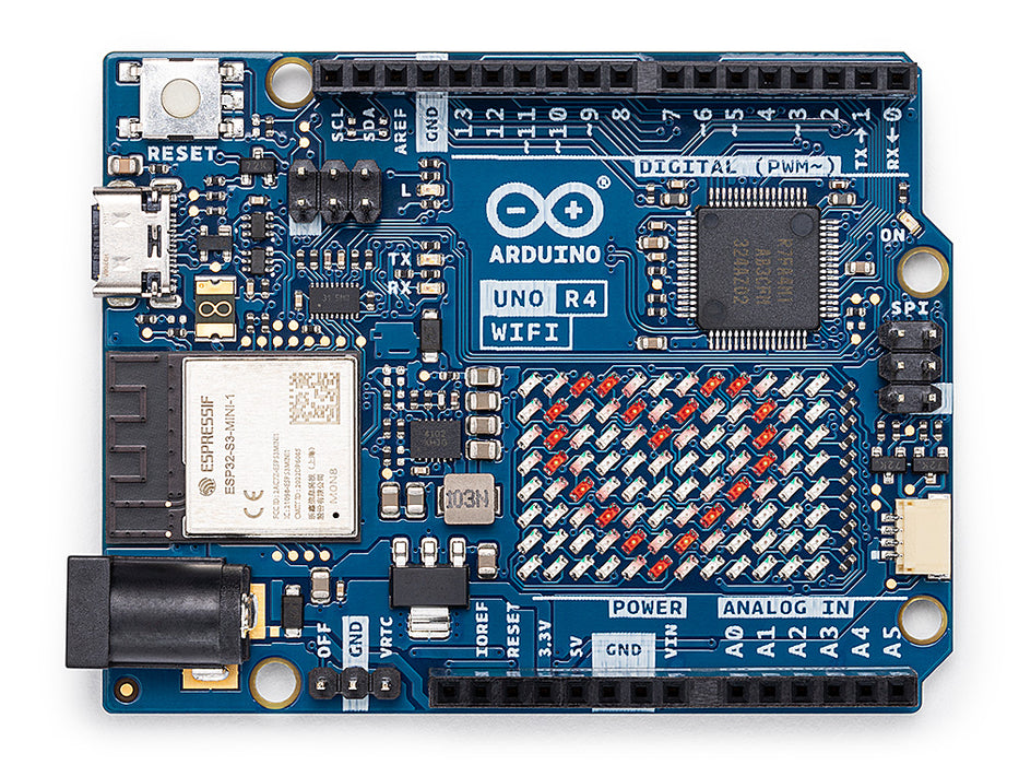
The Arduino Uno R4 WiFi (SKU: ABX00087) is Arduino's official upgrade to the iconic Uno platform. It replaces the classic 8-bit AVR microcontroller with a 32-bit Renesas RA4M1 ARM Cortex-M4 running at 48 MHz, while keeping the same pin layout and form factor that makers and educators have relied on for years.
What sets the R4 WiFi apart from the R4 Minima is the integrated ESP32-S3 wireless coprocessor, which adds Wi-Fi® 802.11 b/g/n and Bluetooth® 5.0 LE without consuming any of the RA4M1's pins or memory. The two chips communicate internally over a dedicated UART link.
On top of connectivity, the board features several capabilities not found on previous Uno boards: a fully addressable 12×8 red LED matrix, a 12-bit DAC for audio output, a Real-Time Clock (RTC) with battery backup, a Qwiic/STEMMA QT connector, and USB-C® for power and programming.
The board operates at 5 V logic and accepts input voltages from 6 to 24 V on the VIN pin, making it compatible with the vast majority of existing Uno shields and accessories.
Quick Overview
- MCU: Renesas RA4M1 (32-bit ARM Cortex-M4 with FPU, 48 MHz)
- Wireless: ESP32-S3 (Wi-Fi® 802.11 b/g/n + Bluetooth® 5.0 LE)
- Flash: 256 KB (RA4M1)
- SRAM: 32 KB (RA4M1)
- Operating Voltage: 5 V
- Input Voltage (VIN): 6–24 V
- Digital I/O Pins: 14
- Analog Input Pins: 6
- PWM Pins: 6
- USB: USB-C®
- Special Features: 12×8 LED Matrix, RTC, 12-bit DAC, Qwiic Connector, OP AMP
Key Features
- 32-bit ARM Cortex-M4 microcontroller with FPU (Renesas RA4M1)
- Integrated ESP32-S3 for Wi-Fi® and Bluetooth® LE — no shield required
- 5 V operating voltage and 5 V logic level — Uno R3 shield compatible
- USB-C® connector for power and programming
- On-board 12×8 red LED matrix (96 individually addressable LEDs, Charlieplexing)
- 12-bit Digital-to-Analog Converter (DAC) for audio and waveform generation
- Real-Time Clock (RTC) with battery backup via VRTC pin
- Qwiic I2C connector for plug-and-play sensor integration
- Operational Amplifier (OP AMP)
- USB HID support (mouse and keyboard emulation)
- OFF pin for software-controlled power management
- Extended input voltage range: 6–24 V
- Compatible with Arduino IDE and most Uno R3 libraries
- 3 months Arduino IoT Cloud Maker plan included
Technical Specifications
| Specification | Value |
|---|---|
| SKU | ABX00087 |
| Main MCU | Renesas RA4M1 |
| Architecture | ARM Cortex-M4 with FPU |
| Clock Speed (RA4M1) | 48 MHz |
| Flash Memory (RA4M1) | 256 KB |
| SRAM (RA4M1) | 32 KB |
| Wireless Module | ESP32-S3 |
| ESP32-S3 ROM / SRAM | 384 KB ROM / 512 KB SRAM |
| Clock Speed (ESP32-S3) | up to 240 MHz |
| Wi-Fi | 802.11 b/g/n (2.4 GHz) |
| Bluetooth | BLE 5.0 |
| Operating Voltage | 5 V |
| Logic Level | 5 V |
| Input Voltage (VIN) | 6–24 V |
| Digital I/O Pins | 14 |
| Analog Input Pins | 6 (12-bit ADC) |
| DAC | 1 × 12-bit |
| PWM Pins | 6 |
| UART | 1 |
| I²C | 1 (+ Qwiic connector) |
| SPI | 1 (ICSP header) |
| USB Interface | USB-C® (native USB HID) |
| On-Board LED Matrix | 12×8 red LEDs (96 total) |
| Dimensions | 68.85 × 53.34 mm |
| Weight | 37 g |
Pinout
https://electronicswiki.com/images/products/arduino-uno-r4-wifi-pinout.png
The Arduino Uno R4 WiFi uses the same pin layout as the Arduino Uno R3. All digital and analog I/O pins operate at 5 V logic, making it compatible with the vast majority of existing Uno shields.
Digital I/O
Pins D0–D13. Pins D3, D5, D6, D9, D10, D11 support PWM output (8-bit). D0 and D1 are shared with UART0 (RX/TX).
Analog Input
Pins A0–A5. 12-bit ADC resolution. A4 and A5 are shared with the I²C bus (SDA/SCL).
Communication Interfaces
| Interface | Pins | Notes |
|---|---|---|
| UART | D0 (RX), D1 (TX) | Also used for serial monitor |
| I²C | SDA (A4), SCL (A5) | Also available on Qwiic connector |
| SPI | D10 (SS), D11 (MOSI), D12 (MISO), D13 (SCK) | Also on ICSP header |
Special Pins
| Pin | Function |
|---|---|
| VIN | 6–24 V external power input |
| 5V | Regulated 5 V output (from USB or VIN) |
| 3.3V | 3.3 V output (max 50 mA) |
| GND | Ground |
| VRTC | Battery backup for RTC (3 V coin cell) |
| OFF | Drive HIGH to cut board power |
Power
| Source | Voltage | Notes |
|---|---|---|
| USB-C | 5 V | Powers board and 5V pin |
| VIN | 6–24 V | Regulated on-board to 5 V |
| 5V Pin | 5 V | Output only (max 800 mA from USB) |
| 3.3V Pin | 3.3 V | Output only (max 50 mA) |
| VRTC Pin | 3 V | Connect coin cell to keep RTC running without main power |
DC Current per I/O Pin: 8 mA maximum. Do not exceed this; always use a transistor or driver IC to switch loads over 8 mA.
OFF Pin: Drive this pin HIGH to disconnect power to the board. Useful for battery-powered projects where a sensor or button should wake the board.
VRTC Pin: Connect a 3 V coin cell (e.g. CR2032) here to keep the RTC running when the board is unpowered.
On-Board Components
- Renesas RA4M1 — main microcontroller (ARM Cortex-M4, 48 MHz)
- ESP32-S3 — wireless coprocessor (Wi-Fi® + Bluetooth® LE)
- 12×8 red LED matrix (96 LEDs, Charlieplexing)
- USB-C® connector for power and programming
- Qwiic / STEMMA QT I2C connector (JST SH 1 mm, 4-pin)
- Reset button
- VRTC pin for RTC battery backup
- OFF pin for power management
- On-board SWD debug interface (2.54 mm header)
- USB-to-serial converter (for serial monitor)
Microcontroller
The Renesas RA4M1 is a 32-bit ARM Cortex-M4 microcontroller from Renesas Electronics, designed for industrial and embedded applications. It is the heart of the Arduino Uno R4 family.
RA4M1 Key Capabilities
- ARM Cortex-M4 core with FPU running at 48 MHz
- 256 KB flash memory, 32 KB SRAM
- 12-bit ADC (up to 14 channels)
- 12-bit DAC (1 channel)
- Real-Time Clock (RTC) with calendar function
- Operational Amplifier (OP AMP)
- USB Full-Speed device (HID, CDC, MSC)
- Multiple timers, PWM channels, and DMA
- Low-power operating modes (Software Standby, Deep Software Standby)
- Hardware security features (AES, SHA)
Wireless Connectivity
The ESP32-S3 module on the Uno R4 WiFi acts as a dedicated wireless coprocessor. The RA4M1 communicates with it over an internal UART using AT commands — the Wi-Fi and Bluetooth stacks run entirely on the ESP32-S3, freeing the RA4M1 for application logic.
Wireless Specs
| Feature | Detail |
|---|---|
| Wi-Fi Standard | 802.11 b/g/n (2.4 GHz only) |
| Bluetooth | Bluetooth® 5.0 LE |
| ESP32-S3 Clock | up to 240 MHz |
| ESP32-S3 Flash | None (relies on internal ROM) |
| ESP32-S3 SRAM | 512 KB |
Libraries
- WiFiS3 — included with the board package, mirrors the classic WiFi API
- ArduinoBLE — Bluetooth LE support
Basic Wi-Fi Connection Example
Firmware Updates
The ESP32-S3 firmware can be updated independently using the Arduino Firmware Uploader utility. Do not interrupt a firmware update — this can brick the wireless module.
LED Matrix
The Uno R4 WiFi features a fully addressable 12×8 red LED matrix (96 LEDs total) driven by Charlieplexing directly from the RA4M1 GPIO pins.
LED Matrix Features
- 96 individually addressable red LEDs in a 12-column × 8-row grid
- Controlled via the Arduino_LED_Matrix library (included with board package)
- Supports static images, scrolling text, and frame-based animations
- No additional hardware or wiring required
Programming the LED Matrix
Arduino provides a LED Matrix Editor tool to design frames and animations visually.
For full tutorials see the official LED Matrix documentation.
Real-Time Clock
The RA4M1 includes a built-in Real-Time Clock (RTC) that tracks date and time and supports configurable alarms.
RTC Features
- Tracks seconds, minutes, hours, day, month, year
- Alarm interrupt support (wake from sleep on a scheduled time)
- Battery backup via VRTC pin — connect a 3 V coin cell to keep time when the board is unpowered
- Supported by the RTC library included with the board package
For full tutorials see the official RTC documentation.
Digital-to-Analog Converter
The RA4M1 includes a single-channel 12-bit DAC accessible on pin A0 in DAC mode.
DAC Features
- 12-bit resolution (4096 discrete output levels)
- Output voltage range: 0 V to 3.3 V
- Suitable for audio waveform generation, analog signal control, and sensor simulation
Basic DAC Example
For full tutorials see the official DAC documentation.
Operational Amplifier
The RA4M1 includes a built-in Operational Amplifier (OP AMP) accessible via dedicated analog pins — no external IC needed.
OP AMP Pin Mapping
| Function | Pin |
|---|---|
| Non-inverting input (+) | A1 |
| Inverting input (−) | A2 |
| Output | A3 |
OP AMP Features
- On-chip OP AMP with no additional components required
- Usable as a voltage follower, inverting or non-inverting amplifier
- Configured via the RA4M1 OPAMP0 peripheral registers or the Arduino analogReference() API
- Useful for conditioning sensor signals before ADC sampling
※ NOTE:
A1, A2, and A3 cannot be used as standard analog inputs at the same time as the OP AMP. Disable the OP AMP peripheral before using those pins for general-purpose ADC.
Qwiic Connector
The board includes a Qwiic / STEMMA QT connector (JST SH 1 mm 4-pin) providing I2C access without soldering.
Qwiic Features
- Connects to the same I2C bus as SDA/SCL pins (A4/A5)
- Compatible with SparkFun Qwiic and Adafruit STEMMA QT ecosystems
- Plug-and-play: no soldering, no power wiring
- Supports multiple devices daisy-chained on one connector
The Qwiic connector operates at 3.3 V. Most Qwiic sensors include on-board level shifters and work correctly with a 5 V I2C bus.
HID Support
The Uno R4 WiFi supports native USB HID (Human Interface Device), allowing it to appear as a keyboard, mouse, or gamepad to a connected computer.
HID Features
- Mouse emulation (movement, click, scroll)
- Keyboard emulation (key press, release, modifiers)
- Gamepad emulation
- Uses the Keyboard, Mouse, and Gamepad libraries included with the board package
- No driver installation required on Windows, macOS, or Linux
※ NOTE:
When the board is in HID keyboard mode, uploading new sketches can be interrupted. Hold the reset button to enter bootloader mode if the board becomes unresponsive.
IoT Cloud
The Uno R4 WiFi is officially supported by Arduino IoT Cloud, Arduino's managed platform for connected devices.
IoT Cloud Features
- Over-the-air (OTA) sketch updates
- Cloud variables — sync variables between the board and the cloud dashboard in real time
- Remote monitoring and control via web dashboard or mobile app
- Webhook and API integrations
- 3 months of Cloud Maker plan included with each board purchase
Get started at Arduino IoT Cloud.
Getting Started
1. Install Arduino IDE
Download and install Arduino IDE 2 (version 2.0 or later recommended).
2. Install the Arduino UNO R4 Board Package
Open Arduino IDE → Tools → Board → Boards Manager → search for Arduino UNO R4 → install Arduino UNO R4 Boards by Arduino.
3. Connect the Board
Connect the Arduino Uno R4 WiFi to your computer using a USB-C® cable. Select:
- Board: Arduino UNO R4 WiFi
- Port: the COM port or /dev/tty* that appears
4. Upload Your First Sketch
Go to File → Examples → 01.Basics → Blink and click Upload. The built-in LED on pin 13 should blink.
5. Enable Wi-Fi
Install the WiFiS3 library (included with the board package). Use File → Examples → WiFiS3 for connection examples.
Programming
- IDE: Arduino IDE 2.x (recommended) or Arduino IDE 1.8.x
- Board Package: Arduino UNO R4 Boards (install via Boards Manager)
- Core: Arduino Renesas Core (based on Renesas FSP)
- Language: C / C++ (Arduino framework)
- Debug Interface: SWD (requires compatible debugger, e.g. J-Link or CMSIS-DAP)
- Bootloader: Built-in USB DFU bootloader (no external programmer needed)
- Serial Monitor: Available via USB-C at any baud rate
The ESP32-S3 firmware can be updated separately using the Arduino Firmware Uploader tool included with the board package.
Shield Compatibility
The Uno R4 WiFi is mechanically and electrically compatible with most Arduino Uno R3 shields. Key compatibility notes:
- All I/O pins operate at 5 V — 5 V-only shields are safe
- Shields requiring the ATmega328P (AVR) registers directly will not work and need porting
- Shields using standard Arduino library APIs (SPI, Wire, Serial) work without modification
- 3.3 V-only shields may require level shifters — the board's 3.3 V output is limited to 50 mA
- Motor shields and other shields drawing more than 800 mA from the 5V pin should use an external power supply via VIN
CAN Bus
The RA4M1 includes a CAN FD (Controller Area Network with Flexible Data-rate) peripheral, accessible on the Arduino Uno R4 WiFi via the CANRX0 / CANTX0 pins.
CAN Bus Pins
| Function | Pin |
|---|---|
| CAN RX | D4 (CANRX0) |
| CAN TX | D5 (CANTX0) |
CAN Bus Features
- CAN FD compliant (ISO 11898-1:2015) — supports both classic CAN (up to 1 Mbit/s) and FD mode (up to 8 Mbit/s data phase)
- Supported by the Arduino_CAN library (install via Library Manager)
- Requires an external CAN transceiver (e.g. MCP2562, SN65HVD230) between the board and the CAN bus — the RA4M1 outputs logic-level signals, not differential CAN signals
Basic CAN Example
Package Contents
- 1× Arduino Uno R4 WiFi board
- 1× USB-C® cable (USB-A to USB-C)
Applications
- IoT and cloud-connected sensor nodes
- Wireless data logging
- Robotics and motion control
- Industrial monitoring and automation
- Audio synthesis and waveform generation (DAC)
- Data visualization on the on-board LED matrix
- Custom USB HID devices (keyboards, gamepads, macro pads)
- Educational and prototyping platforms
- Real-time applications requiring precise timing (RTC)
Equivalent Boards
| Board | Key Difference |
|---|---|
| Arduino Uno R4 Minima | Same RA4M1 MCU, no Wi-Fi/BLE, no LED matrix, lower price |
| Arduino Uno R3 | 8-bit AVR ATmega328P, no wireless, 16 MHz — the classic Uno |
| Arduino Nano ESP32 | ESP32-S3 as main MCU, Nano form factor, 3.3 V logic |
| ESP32 DevKit | ESP32 as main MCU, 3.3 V logic, different pin layout |
| Raspberry Pi Pico W | RP2040 dual-core, MicroPython/C, 3.3 V, built-in Wi-Fi |
| Teensy 4.1 | ARM Cortex-M7 at 600 MHz, no built-in wireless, advanced users |
Documentation
Beginner Tutorials
- Arduino UNO R4 Tutorials — step-by-step guides for sensors, displays, IoT, BLE, and more (English)
- Arduino UNO R4 Tutoriels — same content in French
- Arduino UNO R4 Tutorials — same content in German
- Arduino UNO R4 튜토리얼 — same content in Korean
- Tutoriales Arduino UNO R4 — same content in Spanish
Notes
- The ESP32-S3 operates at 3.3 V internally; the RA4M1 GPIO and power pins operate at 5 V. Do not connect 3.3 V-only devices directly to the RA4M1 GPIO pins without level shifting.
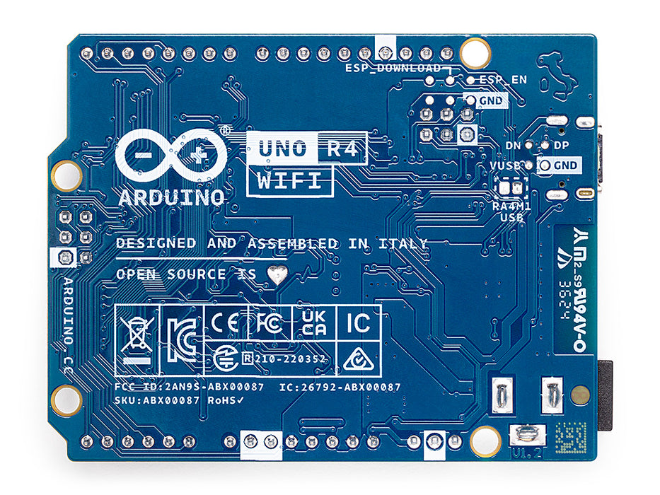
- The ESP32-S3 can be programmed separately via a dedicated header for advanced use cases — this is not normally required.
- Not all AVR-specific (ATmega328P) libraries from Uno R3 are compatible; libraries using direct register access must be ported to the RA4M1 API.
- The LED matrix uses Charlieplexing: avoid modifying the GPIO pins it is connected to while the matrix library is active.
- When using USB HID, the board may become unresponsive to new uploads. Hold the reset button to enter bootloader mode.
- The VRTC pin accepts 1.6–3.6 V. A standard CR2032 coin cell (3 V) is suitable.
- Input voltage on VIN is regulated on-board; voltages above 24 V will damage the board.
Community
- Arduino Forum — Uno R4 WiFi — official community board for questions, projects, and troubleshooting
- Arduino Discord — real-time chat with the Arduino community
- r/arduino (Reddit) — share projects, ask questions, and browse community builds
- Arduino GitHub — Renesas Core — report bugs or follow development of the RA4M1 core
- Arduino Project Hub — browse community-submitted Uno R4 WiFi projects
Revision History
| Version | Date | Notes |
|---|---|---|
| v1.3 | 2026-06 | Added CAN Bus, Operational Amplifier, Beginner Tutorials, Community sections; added Wi-Fi code example; expanded Where to Buy retailers; added LAST_UPDATED metadata |
| v1.2 | 2026-06 | Added Getting Started, Shield Compatibility, Package Contents sections; expanded Overview, Programming, Wireless Connectivity; added documentation URLs; fixed SEO description and keywords |
| v1.1 | 2026-01 | Updated with verified specs; added LED Matrix, RTC, DAC, Qwiic, HID, IoT Cloud sections |
| v1.0 | 2026-01 | Initial entry |