
Arduino Zero
Image Gallery
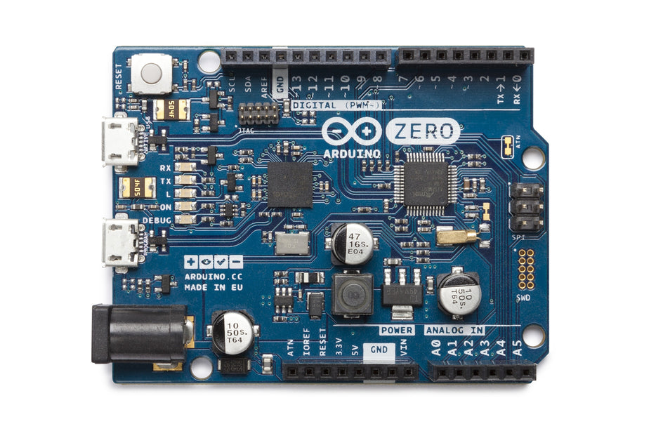
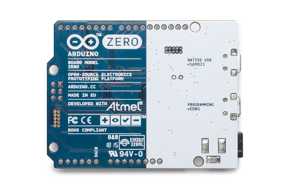
Overview
The Arduino Zero was introduced in 2015 as a bridge between the classic 8-bit AVR Uno and the more powerful 32-bit ARM boards, bringing the ARM Cortex-M0+ architecture into the familiar Arduino Uno form factor for the first time.
At its core is the Atmel ATSAMD21G18A running at 48 MHz, with 256 KB of flash and 32 KB of SRAM. The board operates at 3.3V I/O logic — a departure from the 5V standard of the Uno and Mega — and adds a 10-bit DAC, a 12-bit ADC, and native USB HID support via a dedicated Native USB port.
The most distinctive feature of the Zero is its embedded Atmel Embedded Debugger (EDBG): a full on-board hardware debugger that enables step-through debugging, breakpoints, and variable inspection directly in the Arduino IDE or Atmel Studio, without any external debug probe. This made the Zero the first Arduino to offer professional-grade debugging capabilities.
The Zero has since been discontinued, with the Arduino UNO R4 Minima and Nano 33 IoT serving as its functional successors.
Critical notice: The Zero operates at 3.3V logic. Its I/O pins are NOT 5V tolerant. Connecting 5V signals to I/O pins will damage the SAMD21 microcontroller.
Quick Overview
| Property | Value |
|---|---|
| Microcontroller | ATSAMD21G18A (32-bit ARM Cortex-M0+) |
| Clock Speed | 48 MHz |
| Operating Voltage | 3.3V (NOT 5V tolerant on I/O) |
| Input Voltage (recommended) | 7–12V |
| Digital I/O Pins | 14 (10 with PWM) |
| Analog Input Pins | 6 (12-bit ADC) |
| Analog Output (DAC) | 1 × 10-bit (pin A0) |
| Flash Memory | 256 KB |
| SRAM | 32 KB |
| Hardware UART | 1 |
| USB Ports | 2 × micro-USB (Programming + Native USB) |
| On-Board Debugger | EDBG (Atmel Embedded Debugger — SWD) |
| Form Factor | Arduino Uno |
| Dimensions | 68.6 × 53.3 mm |
Key Features
- 32-bit ARM Cortex-M0+ at 48 MHz in the Arduino Uno form factor
- On-board EDBG hardware debugger — step-through debugging without an external probe
- 12-bit ADC on all 6 analog inputs for high-resolution sensor readings
- 10-bit DAC on pin A0 for true analog voltage output
- Native USB port with HID support (keyboard, mouse, MIDI)
- Programming USB port independent from the Native USB port
- 256 KB flash and 32 KB SRAM — significantly more than the Uno
- Compatible with many Uno-sized shields (physical fit matches; verify 3.3V logic levels)
- Supported by the Arduino IDE via the Arduino SAMD Boards package
Technical Specifications
| Specification | Value |
|---|---|
| Microcontroller | Atmel ATSAMD21G18A |
| Architecture | 32-bit ARM Cortex-M0+ |
| Clock Speed | 48 MHz |
| Operating Voltage | 3.3V |
| Recommended Input Voltage | 7–12V |
| Digital I/O Pins | 14 |
| PWM Pins | 10 (D2–D13, excluding D5 and D7 — verify per silkscreen) |
| Analog Input Pins | 6 (12-bit ADC, A0–A5) |
| Analog Output (DAC) | 1 × 10-bit (A0) |
| DC Current per I/O Pin | 7 mA |
| Flash Memory | 256 KB |
| SRAM | 32 KB |
| Hardware UART | 1 (Serial1, D0 RX / D1 TX) |
| USB | 2 × micro-USB (Programming port + Native USB port) |
| On-Board Debugger | EDBG (Atmel SWD, USB CDC debug port) |
| I2C | 1 (D4 SDA / D5 SCL) |
| SPI | 1 (ICSP header) |
| Dimensions | 68.6 × 53.3 mm |
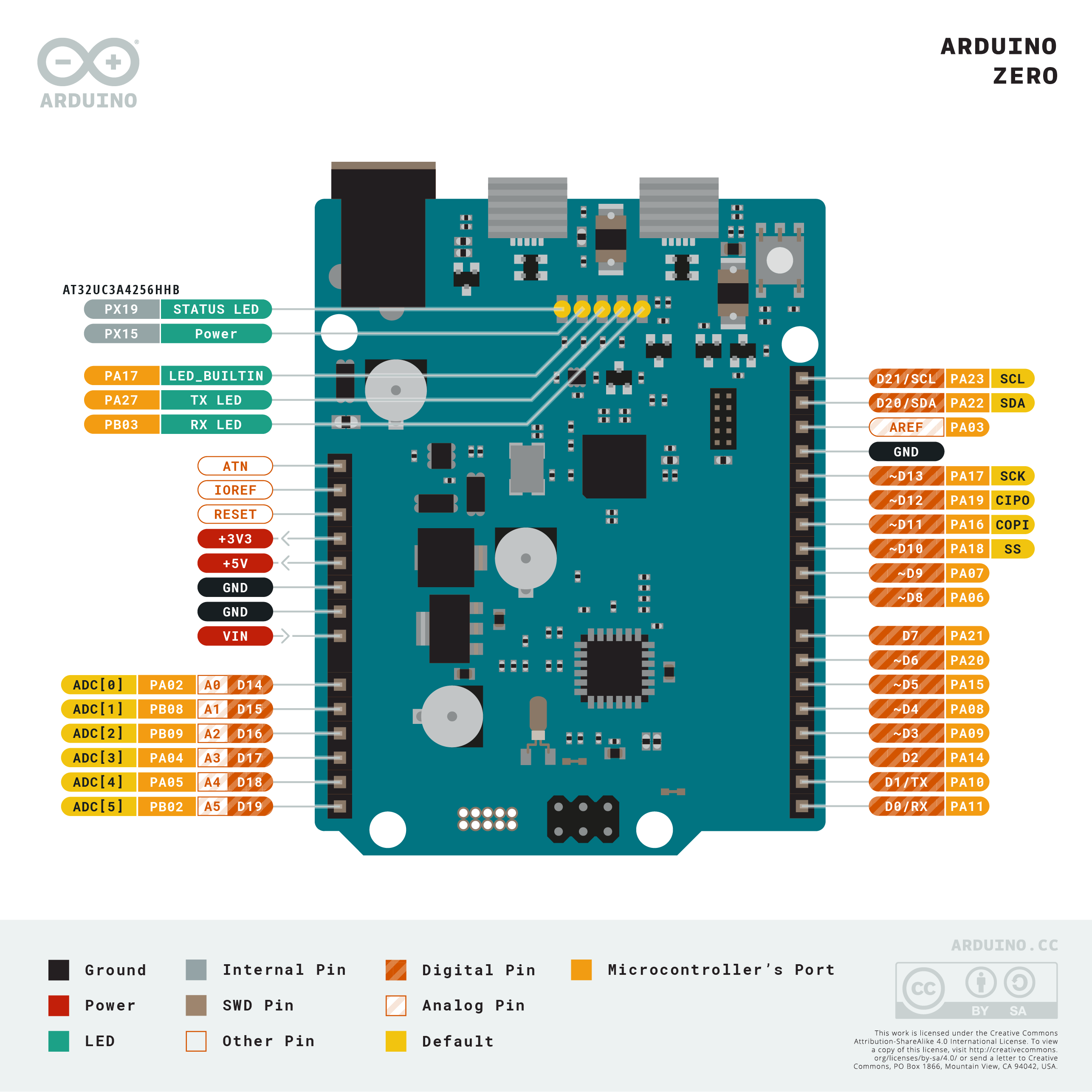
Pinout
Digital I/O Pins
| Pin | Function | Notes |
|---|---|---|
| D0 (RX) | Hardware Serial1 RX | Also general digital I/O |
| D1 (TX) | Hardware Serial1 TX | Also general digital I/O |
| D2–D13 | General digital I/O | PWM on most (10 total PWM pins) |
| D4 | SDA (I2C) | I2C data line |
| D5 | SCL (I2C) | I2C clock line |
Analog Pins
| Pin | Function | Notes |
|---|---|---|
| A0 | Analog input + DAC output | 10-bit DAC, 12-bit ADC |
| A1–A5 | Analog input | 12-bit ADC |
Power Pins
| Pin | Description |
|---|---|
| VIN | 7–12V input |
| 5V | 5V output (for powering peripherals — NOT for I/O logic) |
| 3.3V | 3.3V regulated output |
| GND | Ground |
| RESET | Pull LOW to reset |
| IOREF | 3.3V reference |
| AREF | Analog reference for ADC |
Debug Header
The EDBG exposes a USB CDC debug port on the Programming micro-USB connector, separate from the upload interface. This allows simultaneous serial debugging and sketch upload without switching cables.
Power
The Arduino Zero can be powered by:
- Programming micro-USB: 5V from the host. Standard for development.
- Native micro-USB: 5V from host when using the Native USB port.
- DC Barrel Jack: 7–12V DC, regulated on-board to 3.3V.
- VIN Pin: Same range as the barrel jack.
The Zero's I/O pins operate at 3.3V. Although a 5V line is available on the headers (sourced from USB or the barrel jack regulator), it must not be fed back into any I/O pin.
Microcontroller
The ATSAMD21G18A is a Cortex-M0+ processor from Atmel (now Microchip), targeting low-power embedded applications.
| Attribute | Value |
|---|---|
| Core | ARM Cortex-M0+ |
| Clock | 48 MHz (from 32.768 kHz crystal via DFLL × 1464) |
| Flash | 256 KB with ECC |
| SRAM | 32 KB |
| ADC | 12-bit, up to 350 ksps |
| DAC | 10-bit, 350 ksps |
| USB | Full-speed USB 2.0 device |
| DMA | 12-channel DMAC |
The Cortex-M0+ is the simplest and most power-efficient core in the Cortex-M family. It lacks a hardware floating-point unit (FPU) — floating-point operations are performed in software. For FPU-equipped Uno-class boards, the UNO R4 Minima (Cortex-M4 with FPU) is the recommended successor.
Digital-to-Analog Converter
The Zero provides a single 10-bit DAC channel on pin A0.
| Channel | Pin | Resolution | Output Range |
|---|---|---|---|
| DAC0 | A0 | 10-bit (0–1023) | 0–3.3V |
HID Support
The Zero's Native USB port supports USB HID natively via the SAMD21's built-in USB controller.
Upload HID sketches via the Programming port to avoid losing the upload connection when the board re-enumerates as a HID device.
Getting Started
What You Need
- Arduino Zero
- Micro-USB cable (one for Programming port; optionally one for Native USB port)
- Computer with Arduino IDE installed
Steps
- Connect the Programming port (micro-USB closest to the EDBG chip) to your computer.
- Open the Arduino IDE.
- Install the SAMD board package: Tools > Board > Boards Manager, search for "Arduino SAMD Boards" and install.
- Select Tools > Board > Arduino SAMD Boards > Arduino Zero (Programming Port).
- Select the correct COM port under Tools > Port.
- Upload a sketch.
Blink Example
Programming
The Zero has two upload paths:
| Port | Description |
|---|---|
| Programming Port | Upload via EDBG; supports step-through debugging in Atmel Studio / Arduino IDE |
| Native USB Port | Direct SAMD21 USB; use for HID sketches; 1200-baud touch triggers DFU |
- Board package: Arduino SAMD Boards (Boards Manager)
- Bootloader: SAM-BA bootloader (accessed via Programming port's EDBG)
- Debugging: EDBG supports SWD debugging; Arduino IDE 2.x supports on-board debugging for SAMD21 boards
Shield Compatibility
WARNING: The Zero uses 3.3V I/O logic. Pins are NOT 5V tolerant. Standard 5V Arduino Uno shields will expose the SAMD21 to 5V signals, which can permanently damage the microcontroller.
| Shield Type | Compatibility |
|---|---|
| 5V Arduino Uno / Mega shields | NOT compatible without level shifting — will damage the SAMD21 |
| 3.3V shields | Compatible |
| Shields using analog signals only | Check output voltages; must be within 0–3.3V range |
| Shields that are purely passive (resistors, buttons) | Generally compatible; verify pull-up voltages |
Always verify that every signal line on a shield operates within the 0–3.3V range before connecting it to the Zero. Level-shifting modules are required for interfacing with 5V devices.
Package Contents
| Item | Quantity |
|---|---|
| Arduino Zero board | 1 |
micro-USB cables are not included. Two are useful — one for the Programming port and one for the Native USB port.
Applications
- Learning 32-bit ARM development in a familiar Uno form factor
- Projects requiring on-board step-through debugging (EDBG is ideal for education)
- Precision analog output using the 10-bit DAC (sensor simulation, audio)
- USB HID device development
- Low-power sensor nodes (Cortex-M0+ is more power-efficient than AVR at comparable speeds)
- Projects requiring 12-bit ADC resolution on analog inputs
- Prototyping for production targets using SAMD21-based custom PCBs
Where to Buy
The Arduino Zero is discontinued. New stock may be available from resellers; check Amazon and electronics distributors.
Equivalent Boards
| Board | Key Difference |
|---|---|
| Arduino UNO R4 Minima | Cortex-M4 at 48 MHz with FPU, 5V logic, active production, same Uno form factor |
| Arduino Due | Cortex-M3 at 84 MHz, Mega form factor, dual DAC, 3.3V logic, active production |
| Arduino Nano 33 IoT | Cortex-M0+ (SAMD21), same MCU, smaller form factor, integrated Wi-Fi/BT |
Notes
- The Zero is discontinued. The Arduino UNO R4 Minima is the recommended current-production Uno-form-factor upgrade, offering a Cortex-M4 with FPU and 5V logic compatibility.
- 3.3V I/O only: This is the most critical operational constraint of the Zero. Every peripheral and shield must be verified to operate within 3.3V signal levels.
- The EDBG chip on the Zero serves double duty: it provides the USB-to-serial bridge for the Programming port AND acts as the SWD debug probe. This eliminates the need for any external debugger hardware.
- The 5V pin on the headers is powered from USB/regulator and can be used to supply 5V to peripherals (like 5V sensors with open-drain or isolated outputs), but must never be connected to an I/O pin.
- When using the Arduino IDE 2.x, the Zero supports interactive step-through debugging via the Debug button in the toolbar — one of the only Uno-form-factor boards to offer this.
Community
- Arduino Forum — official community for questions and projects
- Arduino Discord — real-time chat with the Arduino community
- r/arduino (Reddit) — share projects and ask questions
- Arduino Project Hub — browse community-submitted projects
Revision History
| Version | Date | Notes |
|---|---|---|
| v1.0 | 2026-06 | Initial entry |