
DIYables 2.4 Inch TFT LCD Display Module 320x240 SPI ST7789
Image Gallery
Overview
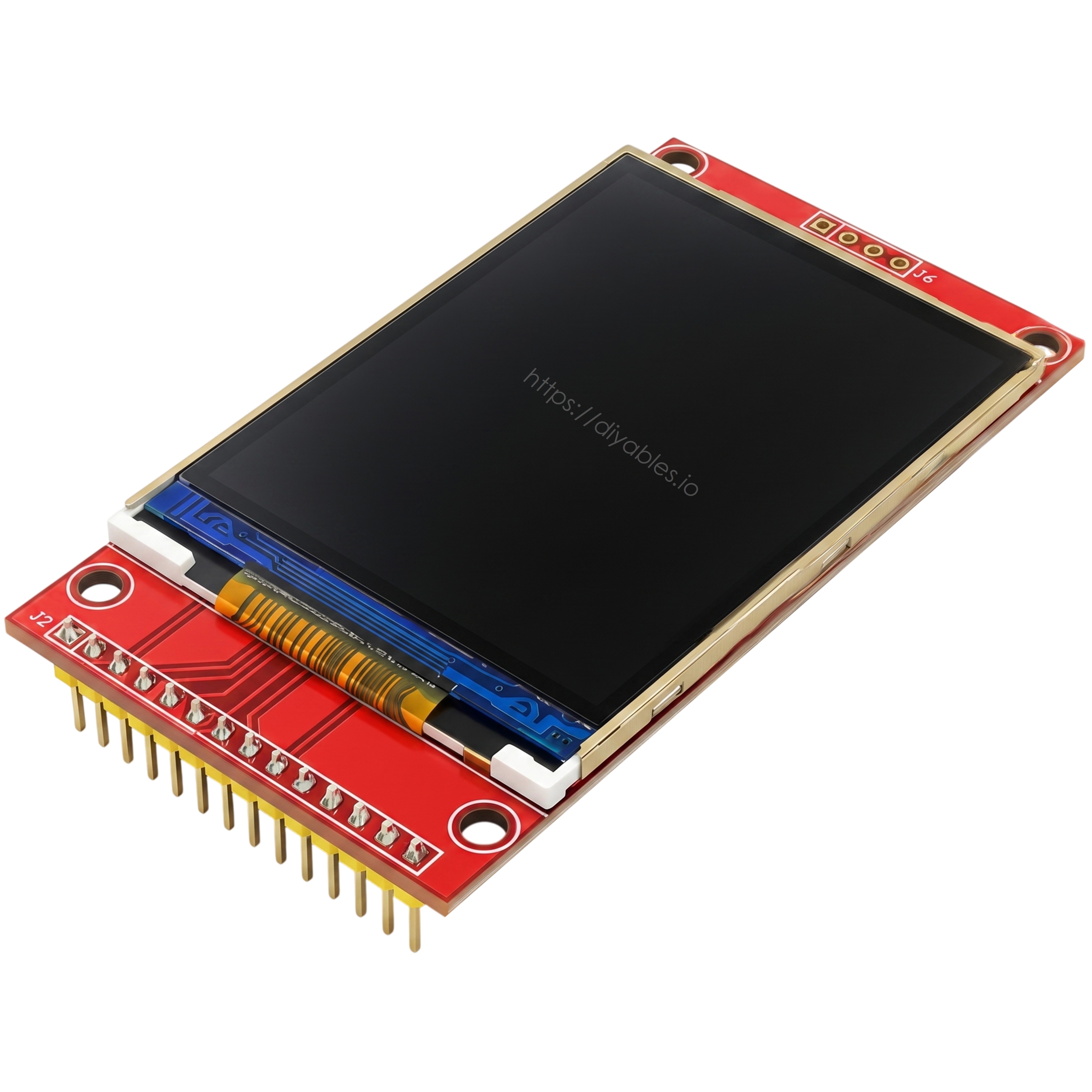
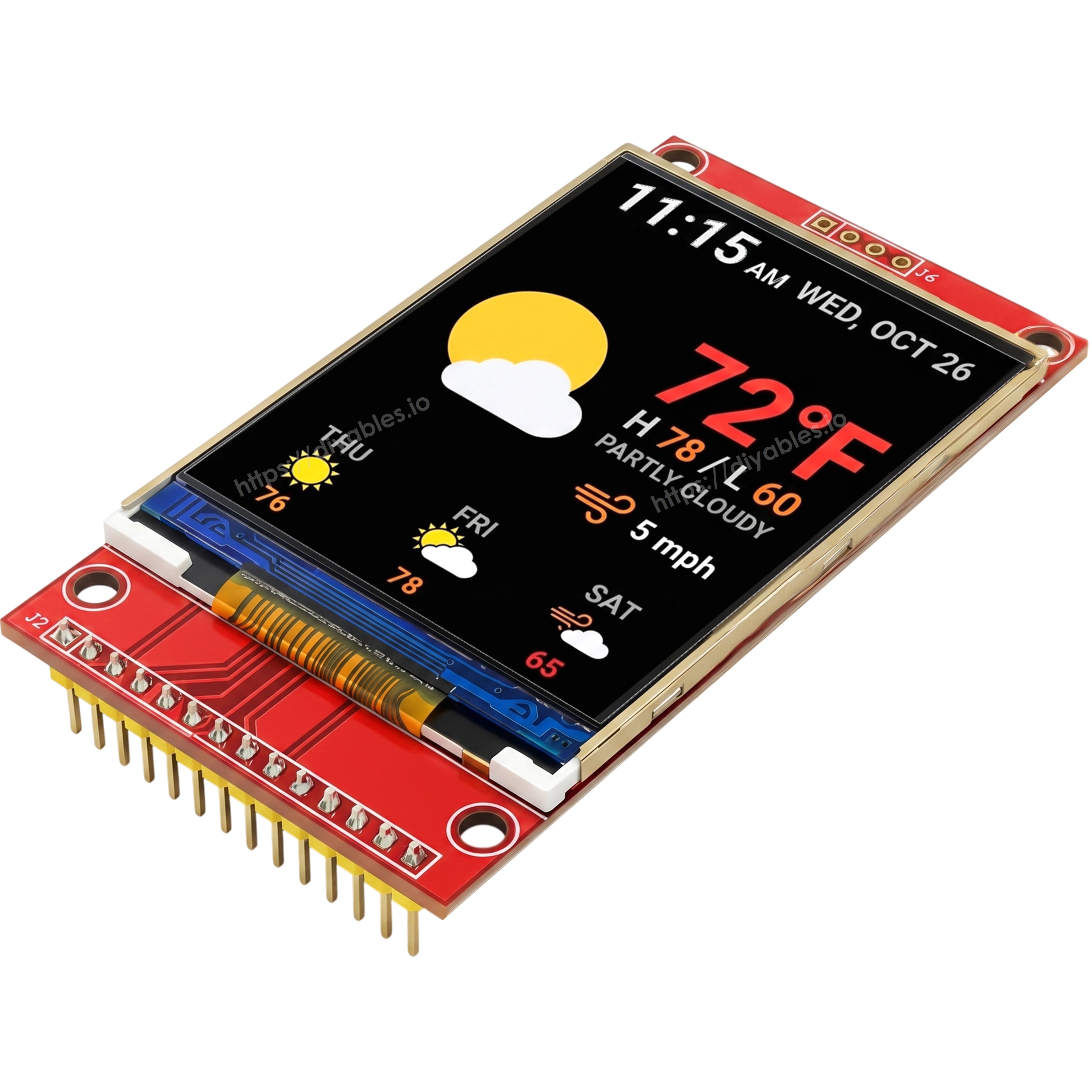
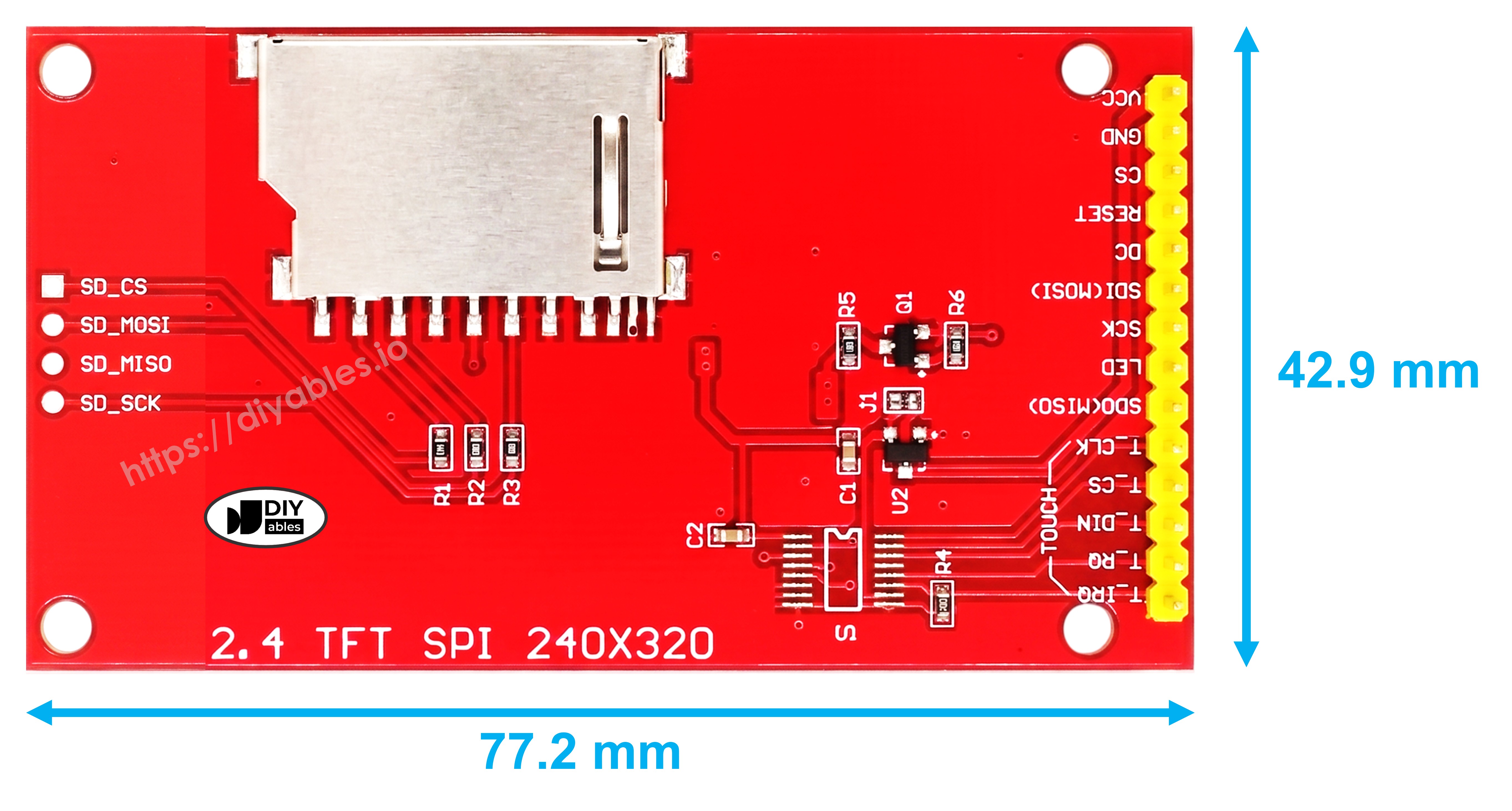
The DIYables 2.4 Inch TFT LCD Display Module delivers a 320×240 QVGA color screen driven by the ST7789 controller over 4-wire SPI. The non-touch design focuses on display output, offering a compact footprint and straightforward integration with Arduino, ESP32, ESP8266, and Raspberry Pi projects. Active area measures 36.72mm × 48.96mm on a 77.18mm × 42.72mm PCB with 2.54mm pin pitch for breadboard compatibility.
The display logic level is 3.3V. When using 5V microcontrollers, a level shifter is required on MCU-driven lines (MOSI, SCK, CS, DC, RST). MISO does not need conversion.
Quick Overview
| Property | Value |
|---|---|
| Display Size | 2.4 inches diagonal |
| Resolution | 320 × 240 pixels (QVGA) |
| Display Type | TFT LCD |
| Driver IC | ST7789 |
| Interface | 4-wire SPI |
| Touch | None |
| Color Depth | 65K colors (16-bit) |
| Active Area | 36.72mm × 48.96mm |
| PCB Dimensions | 77.18mm × 42.72mm |
| Pin Pitch | 2.54mm |
| Operating Voltage | 3.3V – 5V |
| Backlight | White LED |
Key Features
65K-Color TFT Panel
Full RGB 16-bit color output for rich graphics, icons, and data visualization.
Compact SPI Interface
4-wire SPI reduces GPIO usage and is natively supported across all major microcontroller families.
Non-Touch Display-Only Design
No touch layer simplifies hardware and library usage while keeping cost low.
Breadboard-Compatible Pin Pitch
2.54mm headers fit standard breadboards and prototyping setups directly.
Technical Specifications
| Parameter | Value |
|---|---|
| Display Size | 2.4 inch diagonal |
| Resolution | 320 × 240 pixels |
| Driver IC | ST7789 |
| Interface | 4-wire SPI |
| Touch | None |
| Color Depth | 65K colors (RGB565) |
| Active Area | 36.72mm × 48.96mm |
| PCB Dimensions | 77.18mm × 42.72mm |
| Pin Pitch | 2.54mm |
| Operating Voltage | 3.3V – 5V |
| Logic Level | 3.3V |
| Backlight | White LED |
Pinout
| Pin | Description |
|---|---|
| VCC | Power supply (3.3V or 5V) |
| GND | Ground |
| CS | SPI chip select (active LOW) |
| RESET | Display hardware reset |
| DC | Data / Command select (HIGH = data, LOW = command) |
| MOSI | SPI data from MCU to display |
| SCK | SPI clock |
| LED | Backlight enable (connect to VCC or PWM pin) |
Power
Accepts 3.3V or 5V on VCC. Signal lines operate at 3.3V logic — use a level shifter on MOSI, SCK, CS, DC, and RESET when using 5V boards. The LED pin controls backlight; tie to VCC for always-on or connect to a PWM pin for brightness control.
Getting Started
Compatible Boards
Arduino UNO (R3, R4 variants), Mega, Nano, ESP32, ESP8266, Raspberry Pi, Raspberry Pi Pico.
Libraries
Applications
- Sensor data dashboards
- Simple GUI menus
- Status and monitoring displays
- Weather station readouts
- IoT device screens
- Prototyping and development displays
Equivalent Boards
| Module | Key Difference |
|---|---|
| 2.4" Touch TFT ST7789 | Same driver, adds resistive touch and SD card slot |
| 3.5" TFT ILI9486 Shield | Larger, 8-bit parallel, shield form factor |
| 1.28" Round TFT GC9A01 | Circular IPS panel, smaller, SPI |
| OLED 128x64 | Monochrome, no backlight needed, lower power |
Beginner Tutorials
Notes
- Logic level is 3.3V — use a level shifter for 5V boards on all MCU-driven lines.
- The LED pin can be driven by a PWM output for dimming control.
- Start SPI at 40 MHz and reduce if display artifacts appear.
Community
Revision History
| Version | Date | Notes |
|---|---|---|
| v1.0 | 2026-06 | Initial entry |