
1602A LCD Display Module, Blue Screen
Image Gallery
Overview
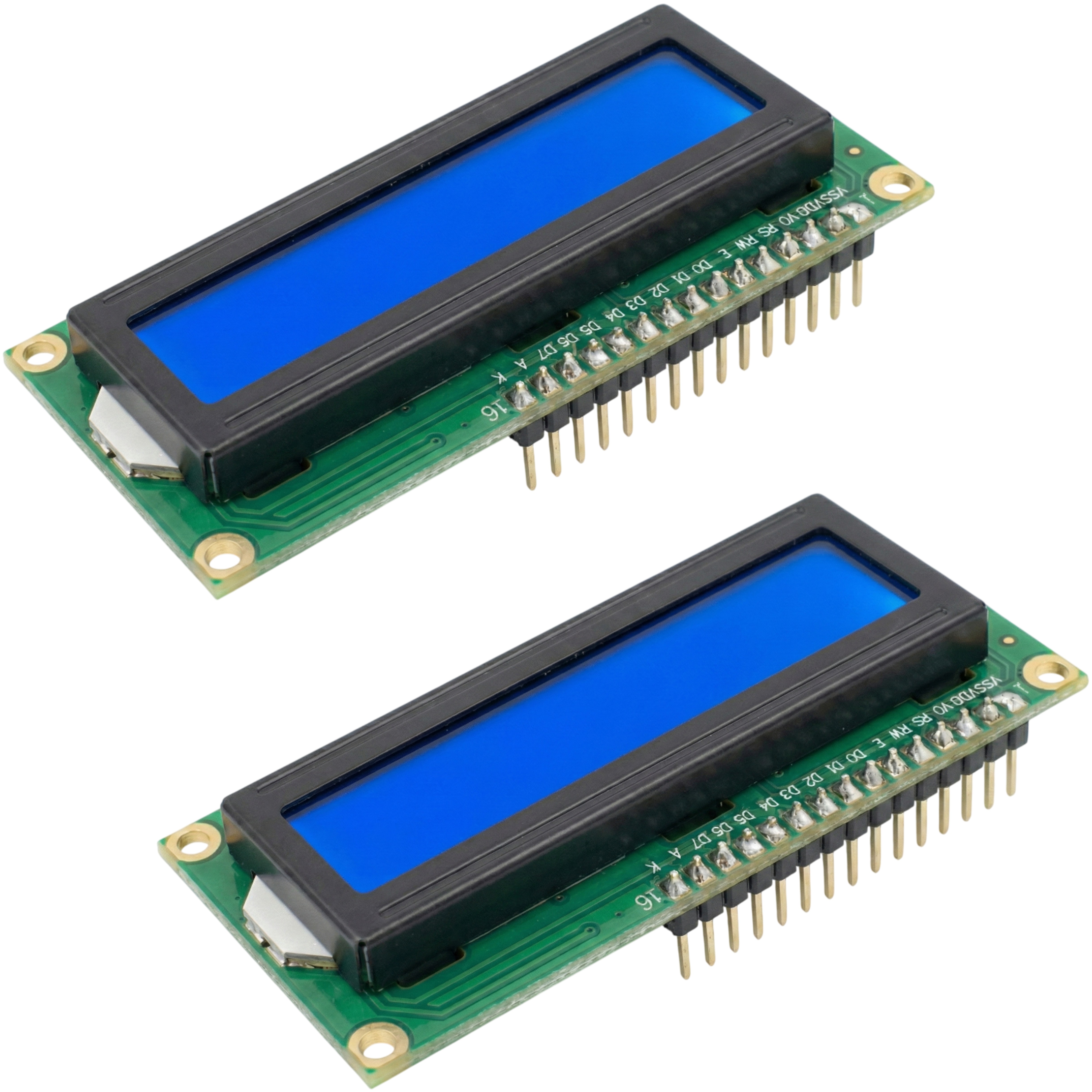
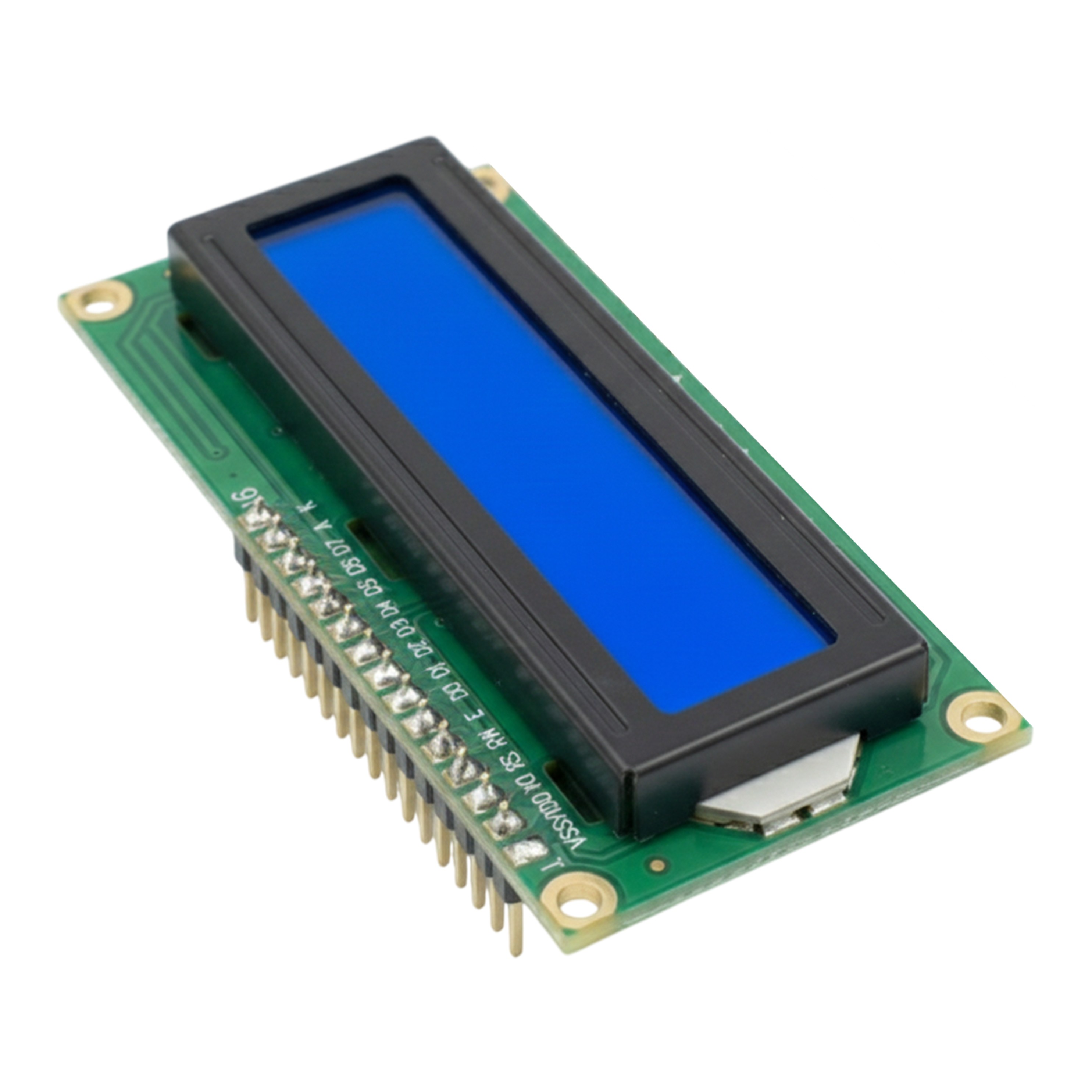
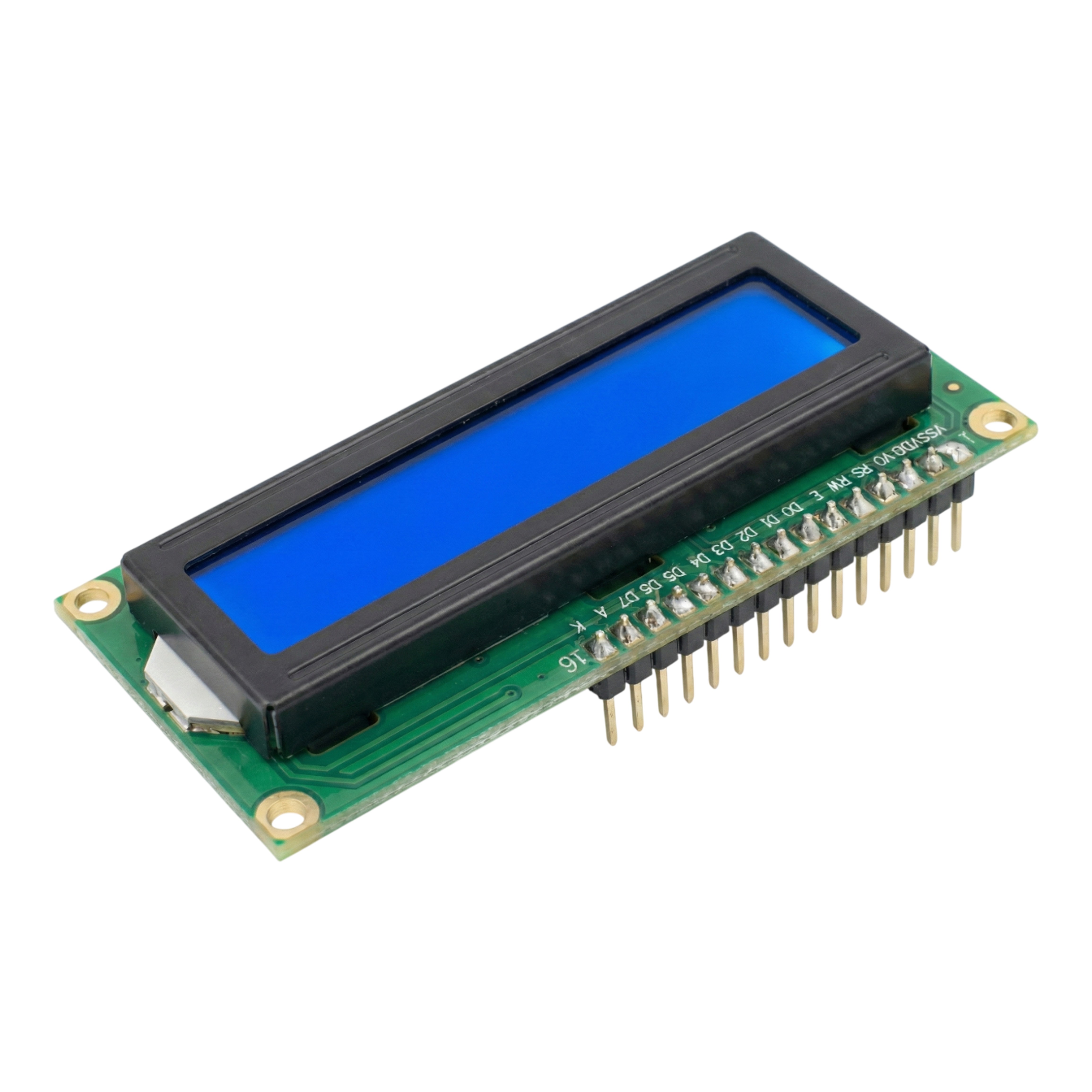
The DIYables 1602A LCD Display Module is a classic 16-character by 2-row character LCD featuring a blue backlight with white text. The module uses an HD44780-compatible controller with a standard 16-pin parallel interface and includes pre-soldered pin headers for direct breadboard use. Package contains 2 pieces.
Unlike I2C LCD variants, this module connects directly via a parallel data bus (4-bit or 8-bit mode) and requires more GPIO pins but no I2C expander. A built-in potentiometer allows contrast adjustment.
Quick Overview
| Property | Value |
|---|---|
| Model | 1602A |
| Display Format | 16 characters × 2 rows |
| Controller | HD44780 compatible |
| Character Matrix | 5 × 8 dots per character |
| Display Color | White characters on blue background |
| Backlight | Blue LED (5V) |
| Interface | 16-pin parallel (4-bit or 8-bit mode) |
| Operating Voltage | 5V DC |
| Logic Level | 5V TTL |
| Contrast | Potentiometer-adjustable |
| Dimensions | 80mm × 36mm × 13mm |
| Package | 2 pieces |
Key Features
HD44780 Controller
Industry-standard controller ensures compatibility with the Arduino LiquidCrystal library and extensive tutorials.
4-Bit or 8-Bit Parallel Mode
4-bit mode requires only 6 GPIO lines (RS, EN, D4–D7) instead of 10.
Adjustable Contrast
Onboard potentiometer sets LCD contrast; turn counterclockwise if only black squares are visible.
Pre-Soldered Headers
16-pin headers arrive soldered, ready for breadboard insertion.
Technical Specifications
| Parameter | Value |
|---|---|
| Model | 1602A |
| Display Type | Character LCD (alphanumeric) |
| Layout | 16 characters × 2 rows |
| Character Matrix | 5 × 8 dots |
| Display Controller | HD44780 compatible |
| Interface | Parallel (16-pin) |
| Data Mode | 4-bit or 8-bit |
| Operating Voltage (VDD) | 5V DC |
| Logic Level | 5V TTL |
| Backlight | Blue LED, 5V |
| Display Color | White characters on blue background |
| Contrast | Potentiometer on module |
| Operating Temperature | 0°C to 50°C |
| Dimensions | 80mm × 36mm × 13mm |
| Package | 2 pieces |
Pinout
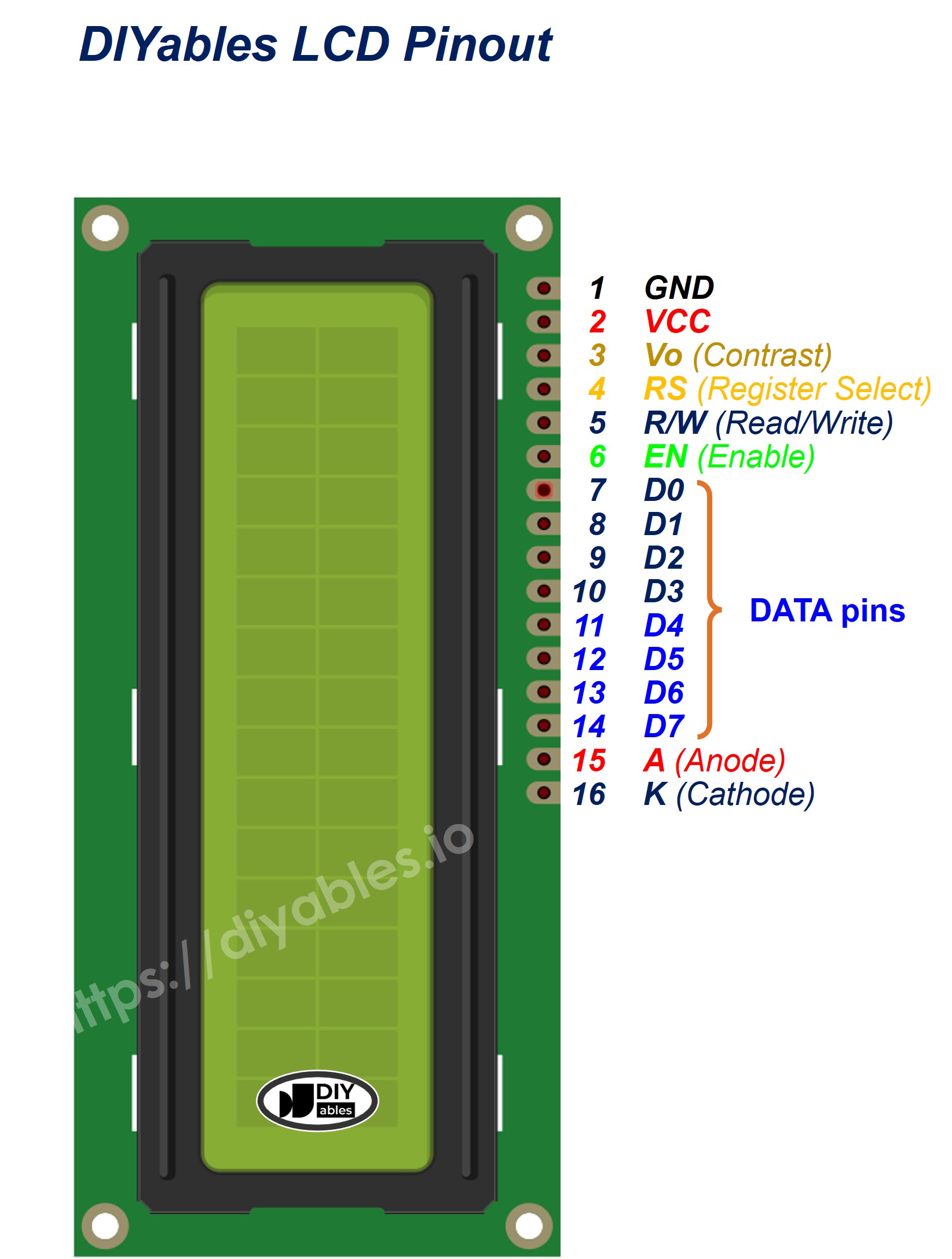
| Pin | Label | Description |
|---|---|---|
| 1 | VSS | Ground (0V) |
| 2 | VDD | Power supply (5V) |
| 3 | V0 | Contrast — connect to potentiometer wiper |
| 4 | RS | Register Select (LOW = command, HIGH = data) |
| 5 | R/W | Read/Write (connect to GND for write-only) |
| 6 | E | Enable clock signal |
| 7–10 | D0–D3 | Data bits 0–3 (unused in 4-bit mode) |
| 11–14 | D4–D7 | Data bits 4–7 |
| 15 | A | Backlight anode (5V via 100Ω or directly if resistor onboard) |
| 16 | K | Backlight cathode (GND) |
Power
Requires 5V on VDD. LED backlight anode (pin 15) connects to 5V through a current-limiting resistor (~100Ω) or directly if the module includes an onboard resistor. For 3.3V systems, use a level shifter for data and control lines.
Getting Started
Wiring (4-bit mode, Arduino Uno)
| LCD Pin | Arduino Pin |
|---|---|
| 1 (VSS) | GND |
| 2 (VDD) | 5V |
| 3 (V0) | Potentiometer wiper |
| 4 (RS) | D12 |
| 5 (R/W) | GND |
| 6 (E) | D11 |
| 11 (D4) | D5 |
| 12 (D5) | D4 |
| 13 (D6) | D3 |
| 14 (D7) | D2 |
| 15 (A) | 5V (via 100Ω) |
| 16 (K) | GND |
Libraries
- LiquidCrystal — built-in Arduino library
Applications
- Sensor and measurement readouts
- Menu systems
- Status and diagnostic displays
- Educational electronics projects
- Timer and counter displays
- Industrial panel indicators
Equivalent Boards
| Module | Key Difference |
|---|---|
| LCD I2C 16x2 | Same display with I2C backpack — only 4 wires needed |
| LCD I2C 16x2 Blue Background | I2C version, blue backlight |
| LCD Keypad Shield | Includes 5 navigation buttons, shield form factor |
| LCD 20x4 I2C | Larger 4-row display with I2C interface |
Beginner Tutorials
Notes
- If display shows only black squares on top row, turn the contrast potentiometer counterclockwise.
- Connect R/W (pin 5) to GND for write-only mode — the standard approach.
- 3.3V microcontrollers should use level shifters on RS, EN, and D4–D7.
- The LiquidCrystal library uses 4-bit mode when only four data pins are specified.
Community
Revision History
| Version | Date | Notes |
|---|---|---|
| v1.0 | 2026-06 | Initial entry |