Raspberry Pi Pico
Image Gallery
Overview
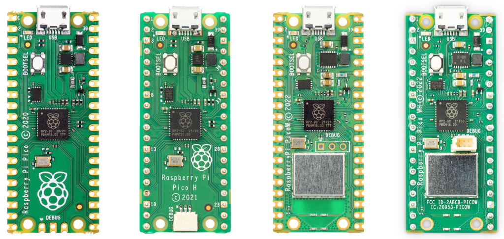
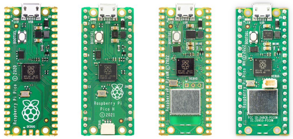
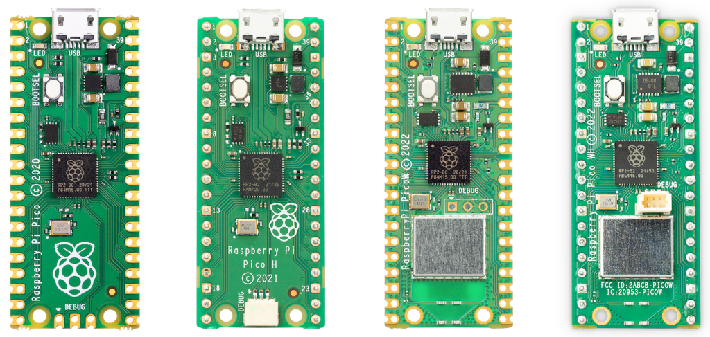
The Raspberry Pi Pico is Raspberry Pi's first microcontroller board and the debut product built around the RP2040 — the organisation's own custom silicon. Launched in January 2021, it brought a capable dual-core ARM Cortex-M0+ microcontroller to market at approximately $4 USD, making it one of the most cost-effective platforms for embedded development available.
The RP2040 was designed entirely by Raspberry Pi and manufactured on a 40 nm process. It pairs two Cortex-M0+ cores running at up to 133 MHz with 264 KB of SRAM spread across six independent banks, allowing both cores and the DMA controller to operate with reduced bus contention. Flash memory is not on the chip itself — the Pico uses a 2 MB QSPI Flash device soldered separately, which is one reason the RP2040 can be used in modules with different Flash sizes.
The most distinctive feature of the RP2040 is its Programmable I/O (PIO) subsystem. Two PIO blocks each contain four state machines that execute compact assembly programs in hardware, entirely independent of the processor cores. This allows the Pico to implement nearly any clocked serial protocol — WS2812 NeoPixel control, stepper motor step generation, custom SPI and I2C variants, I2S audio, and more — purely in software without external protocol chips.
The board ships without pre-soldered headers. Users solder their own 0.1" male or female headers to suit their project. The Pico H variant ships with headers already soldered and adds a 3-pin SWD debug connector.
Key Features
- RP2040 dual-core ARM Cortex-M0+ running up to 133 MHz — Raspberry Pi's own silicon
- 2 MB QSPI Flash (off-chip), 264 KB SRAM (6 independent banks)
- 26 user-accessible GPIO pins via 0.1" headers (30 total on the RP2040)
- 3 × 12-bit ADC channels plus 1 internal temperature sensor ADC channel
- Up to 16 PWM channels across 8 independent slices
- 2 × PIO blocks with 4 state machines each — 8 total user-programmable state machines
- 2 × I2C, 2 × SPI, 2 × UART
- USB 1.1 with built-in controller (device and host mode)
- Micro-USB power or VSYS pin (1.8–5.5 V); on-board 3.3 V switching regulator
- On-board LED on GPIO 25
- No Wi-Fi, no Bluetooth (see Pico W for wireless)
- MicroPython, CircuitPython, C/C++ SDK, and Arduino framework supported
- Compact 51 × 21 mm footprint, 3 g weight
- ~$4 USD
Technical Specifications
| Attribute | Value |
|---|---|
| SKU | SC0915 |
| MCU | RP2040 (dual-core ARM Cortex-M0+) |
| Clock Speed | Up to 133 MHz |
| SRAM | 264 KB (6 independent banks) |
| Flash | 2 MB QSPI (off-chip) |
| GPIO (accessible) | 26 (via 0.1" header) |
| GPIO (RP2040 total) | 30 |
| ADC | 3 × 12-bit + 1 internal temperature sensor |
| PWM Channels | Up to 16 (8 independent slices) |
| PIO | 2 blocks × 4 state machines = 8 total |
| I2C | 2 |
| SPI | 2 |
| UART | 2 |
| USB | USB 1.1 (device and host mode) |
| Wi-Fi | None |
| Bluetooth | None |
| On-board LED | GPIO 25 |
| Operating Voltage | 1.8–5.5 V |
| Power Input | Micro-USB or VSYS pin |
| On-board Regulator | 3.3 V switching regulator |
| Headers | Unpopulated (solder required) |
| Dimensions | 51 × 21 mm |
| Weight | 3 g |
| Release Year | 2021 |
| Price (approx.) | ~$4 USD |
Microcontroller
The Raspberry Pi Pico is built around the RP2040 — the first microcontroller chip designed in-house by Raspberry Pi. It represents a deliberate choice to move beyond using existing silicon and create a device optimised for the kinds of projects the Raspberry Pi community builds.
Dual-Core ARM Cortex-M0+
The RP2040 contains two ARM Cortex-M0+ cores. Each core operates independently and can be clocked at up to 133 MHz. Both cores share access to the same SRAM and peripherals but have independent execution paths, enabling true simultaneous computation.
In MicroPython, the _thread module provides access to Core 1. In the C/C++ SDK, multicore_launch_core1() starts an arbitrary function on Core 1. Typical use patterns place time-sensitive work (PWM generation, protocol handling) on Core 1 while Core 0 manages application logic.
PIO — Programmable I/O
PIO is the RP2040's most unique feature. Each of the two PIO blocks contains four state machines running a specialised instruction set (MOV, IN, OUT, PUSH, PULL, JMP, WAIT, IRQ, SET, NOP) at up to the system clock rate. PIO state machines run entirely in hardware, consuming no CPU cycles and adding no jitter.
PIO programs can implement:
- WS2812 / NeoPixel LED strip control (tight timing requirements met deterministically)
- Stepper motor pulse sequences
- Custom SPI, I2C, UART variants with non-standard speeds or framing
- I2S audio input and output
- DMX512 lighting protocol
- Rotary encoder reading
- VGA or composite video generation (with careful timing)
PIO programs are written in PIO assembly and compiled into 32-instruction program memories at runtime, making the peripheral flexible and reusable across wildly different applications.
USB 1.1 Controller
The RP2040 includes a full-speed USB 1.1 controller supporting both device and host modes with no external transceiver required. In device mode the board can enumerate as a CDC serial port (providing the Python REPL over USB), a HID keyboard or mouse, or a USB mass-storage device. In host mode it can drive keyboards, mice, and other USB 1.1 devices.
The USB controller also powers the built-in UF2 bootloader: hold BOOTSEL while applying power, and the board presents as a USB mass-storage drive. Dropping a .uf2 firmware file onto that drive programs the Flash and reboots automatically.
SRAM Architecture
The 264 KB of SRAM is split into six independent banks connected via a crossbar switch. This means two different masters (e.g., Core 0 and Core 1, or Core 0 and DMA) can simultaneously access different banks without stalling. Stack and data for each core can be placed in separate banks to maximise throughput.
Getting Started
Requirements
- Raspberry Pi Pico board
- Micro-USB cable (data-capable, not charge-only)
- Computer with USB port
- Soldering iron and headers (if using GPIO — board ships unsoldered)
Installing MicroPython
- Download the Pico MicroPython .uf2 from https://www.raspberrypi.com/documentation/microcontrollers/raspberry-pi-pico.html
- Hold the BOOTSEL button on the Pico while connecting the micro-USB cable to your computer
- Release BOOTSEL — the board appears as a USB drive named RPI-RP2
- Drag and drop the .uf2 file onto the drive
- The board reboots automatically and MicroPython is running
- Open Thonny IDE, select the Pico's serial port, and access the REPL
MicroPython Blink Example
The on-board LED on the Pico is directly connected to GPIO 25:
Programming
MicroPython
MicroPython is the most popular language for the Pico. Thonny IDE provides a one-click installer and an integrated REPL for interactive development. The machine module exposes GPIO, PWM, ADC, I2C, SPI, UART, and Timer peripherals. The rp2 module provides access to PIO programming.
C/C++ SDK
The official Raspberry Pi Pico SDK (pico-sdk) is a CMake-based toolchain supporting all RP2040 hardware at the register level. It produces the smallest, fastest binaries and is the standard choice for production firmware. PIO programs are written in .pio files and compiled by the pioasm tool included in the SDK.
CircuitPython
Adafruit's CircuitPython port provides Python development with a different module structure (board, digitalio, analogio, busio). Files are edited directly on the board's USB mass-storage volume, making for a fast edit-save-run cycle.
Arduino
The community arduino-pico core by Earle Philhower adds full Arduino IDE support for the Pico. Most Arduino libraries targeting hardware-independent APIs work without modification. The core also exposes PIO through an rp2040 library.
Applications
- Learning embedded programming (MicroPython and C)
- Sensor data acquisition with ADC, I2C, and SPI sensors
- PWM motor and servo control
- WS2812 NeoPixel and LED matrix driving via PIO
- USB HID devices — keyboards, gamepads, MIDI controllers
- Data loggers writing to SPI Flash or SD cards
- Audio synthesis and I2S interfaces via PIO
- Low-cost industrial controller nodes
- Robotics and autonomous vehicle controllers
Where to Buy
- Raspberry Pi Official — official product page and authorized resellers
- Amazon — search for Raspberry Pi Pico
Equivalent Boards
| Board | Wireless | Headers | Notes |
|---|---|---|---|
| Raspberry Pi Pico W | Wi-Fi + BLE 5.2 | Unpopulated | Adds CYW43439 wireless module; LED on GPIO expander |
| Raspberry Pi Pico 2 | None (Pico 2W for wireless) | Unpopulated | RP2350; faster, more memory, RISC-V option |
| Arduino Nano RP2040 Connect | Wi-Fi + BLE | Pre-soldered | RP2040 in Arduino Nano form factor with u-blox wireless |
Documentation
Notes
- The on-board LED is on GPIO 25 and is directly driven by the RP2040 — unlike the Pico W, where the LED is connected through the CYW43439 GPIO expander.
- The four GPIO pads on the underside of the PCB (GPIO 29 and the ADC reference pad among them) are not accessible from the standard 0.1" header.
- The RP2040 has no internal Flash; all program storage is on the external QSPI Flash chip. The Flash is memory-mapped via XIP (execute-in-place) caching.
- The board's 3.3 V switching regulator (RT6150) can supply up to 300 mA to external peripherals via the 3V3 pin.
- Operating frequency can be configured in software from approximately 48 MHz up to 133 MHz (and beyond with overclocking, though stability is not guaranteed above 133 MHz).
Community
- Raspberry Pi Forums — official community
- r/raspberry_pi (Reddit) — share projects
- Raspberry Pi Discord — real-time chat
Revision History
| Version | Date | Notes |
|---|---|---|
| v1.0 | 2026-06 | Initial entry |